
Automatic equipment vacuum chuck convenient to move

A technology of automation equipment and vacuum suction cups, which is applied in the direction of load hanging components, traveling mechanisms, cranes, etc., can solve the problems that affect the use of suction cups, the limited contact range of workpieces, and the difficulty of installation and disassembly of suction cups, so as to achieve easy installation and disassembly, Expanded reachable range and good adsorption effect

Pending Publication Date: 2022-04-12
苏州精细铧智造科技有限公司
View PDF0 Cites 1 Cited by
  • Summary
  • Abstract
  • Description
  • Claims
  • Application Information

AI Technical Summary

Problems solved by technology

[0004] In this embodiment, a vacuum suction cup for automation equipment that is easy to move is provided to solve the problem that the position of the suction cup in the prior art is not easy to adjust, the contact range with the workpiece is limited, which affects the adsorption of the workpiece, and the suction cup blanking area lacks scalability. The supporting structure is not conducive to the blanking support of the workpiece, and the contact area between the suction cup and the workpiece is insufficient to affect the adsorption effect. The suction cup is not easy to install and disassemble, which affects the use of the suction cup.

Method used


Image

  • Automatic equipment vacuum chuck convenient to move
  • Automatic equipment vacuum chuck convenient to move
  • Automatic equipment vacuum chuck convenient to move

Examples


Embodiment Construction

[0024] In order to enable those skilled in the art to better understand the solution of the present application, the technical solution in the embodiment of the application will be clearly and completely described below in conjunction with the accompanying drawings in the embodiment of the application. Obviously, the described embodiment is only It is an embodiment of a part of the application, but not all of the embodiments. Based on the embodiments in this application, all other embodiments obtained by persons of ordinary skill in the art without creative efforts shall fall within the scope of protection of this application.

[0025] It should be noted that the terms "first" and "second" in the description and claims of the present application and the above drawings are used to distinguish similar objects, but not necessarily used to describe a specific sequence or sequence. It should be understood that the data so used may be interchanged under appropriate circumstances for...


PUM


Abstract

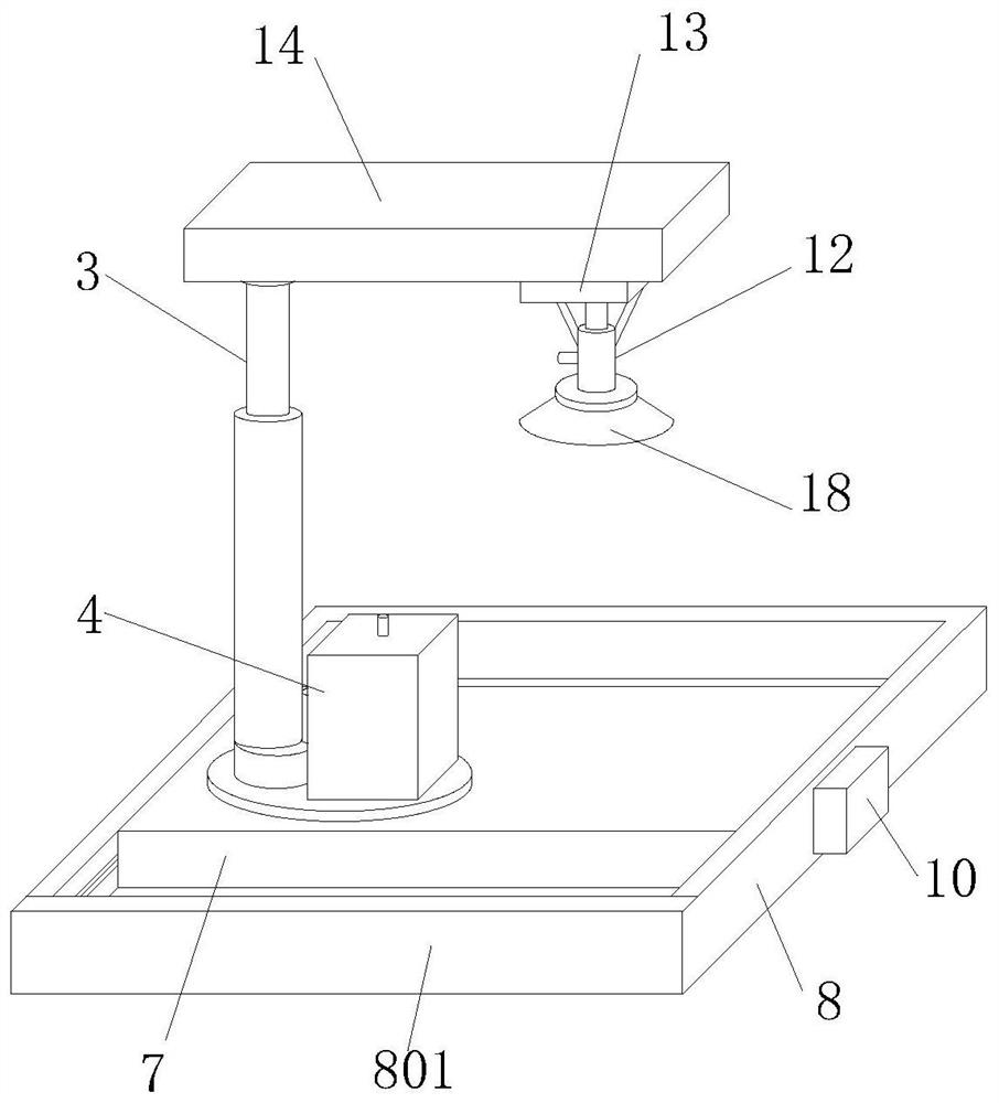
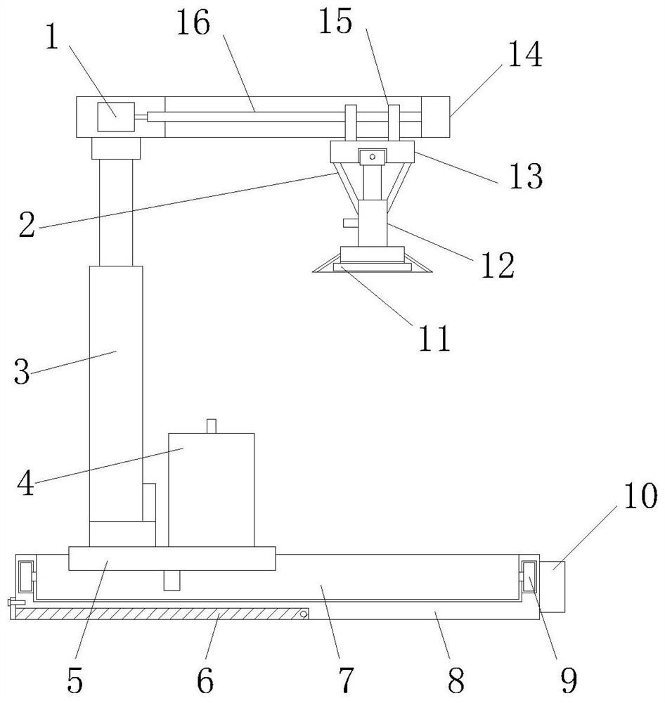
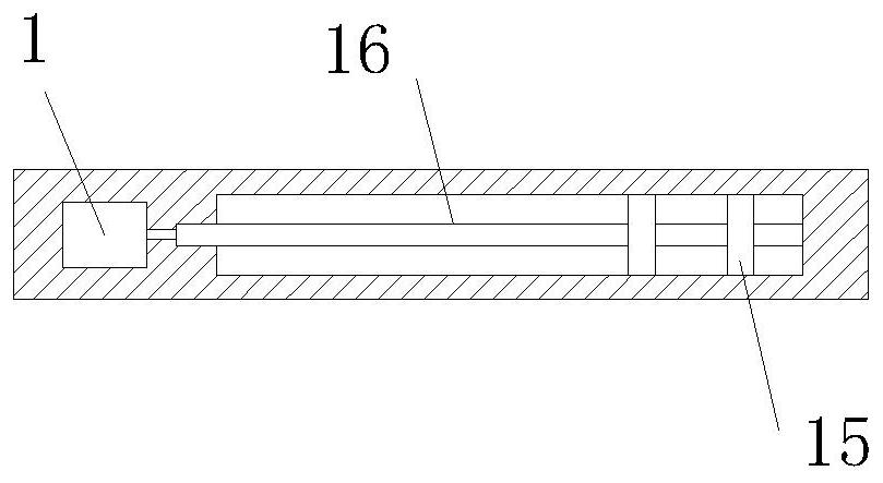
The invention discloses an automatic equipment vacuum chuck convenient to move. Comprising a first motor, a supporting rod, a hydraulic push rod, a vacuum generator, an adjusting disc, an extending plate, a moving plate, a base, a baffle, walking wheels, a control panel, a suction pad, a through hole, a sleeve, a connecting plate, an auxiliary plate, a sleeve plate, a lead screw, a connecting pipe, a suction cup sleeve, a suction cup hoop, a transverse rod, a second motor, a driving disc, a third motor and a gasket. A lead screw can adjust the position of a sucker at the bottom of the auxiliary plate, the sucker can make contact with workpieces conveniently, an adjusting disc can be rotationally adjusted, and the sucker can suck and move the workpieces placed at different positions conveniently; the hydraulic push rod can assist the sucker to adjust the height, the movable plate can move in the base, adjustment of the discharging position of the sucker is facilitated, the extension plate can be stretched for use, and the gasket can support and protect the bottom of a workpiece during discharging. The sucker hoop can reinforce the connection of the suction pad and the sleeve, the sucker sleeve can increase the contact area of the sucker and a workpiece, and the sucker is convenient to mount and dismount.

Description

technical field [0001] The application relates to the field of vacuum suction cups, in particular to a vacuum suction cup for automatic equipment that is easy to move. Background technique [0002] Vacuum suction cup, also known as vacuum spreader, is one of the actuators of vacuum equipment. Generally speaking, using vacuum suction cups to grab products is the cheapest method. Vacuum suction cups are available in a variety of varieties, including those made of rubber that can operate at high temperatures, those made of silicone rubber that are ideal for gripping rough surfaces, and those made of polyurethane that are durable. [0003] The position of the suction cup is not easy to move and adjust, and the contact range with the workpiece is limited, which affects the adsorption of the workpiece. The suction cup blanking area lacks a retractable support structure, which is not conducive to the blanking support of the workpiece, and the insufficient contact area between the ...

Claims


Application Information

Patent Timeline
Patent Type & Authority Applications(China)
IPC IPC(8): B66C23/16B66C23/62B66C23/84B66C1/02B66C9/14
Inventor 陈建强朱俊杰
Owner 苏州精细铧智造科技有限公司
Learn More