
Laminated beam stirrup anti-inclination device with lightweight design

A lightweight design, anti-tilt technology, used in packaging, transportation and packaging, vehicles for freight, etc., can solve the problems of stirrup tilt, carriage impact, increase the damage rate of laminated beams, etc., to avoid fragmentation , Avoid friction, improve the effect of protection

Pending Publication Date: 2022-04-12
常熟市博海新型建材有限公司
View PDF0 Cites 0 Cited by
  • Summary
  • Abstract
  • Description
  • Claims
  • Application Information

AI Technical Summary

Problems solved by technology

[0003] The purpose of the present invention is: in order to solve the situation that the stirrup may be inclined due to the factors of the transportation environment during the transportation process, if the stirrup is inclined, it will affect the fixing effect of the concrete after pouring, and at the same time affect the assembly of the concrete. Moreover, the composite beam cannot be protected during transportation. Hot weather and exposure to the composite beam will increase the brittleness of the composite beam, which will increase the probability of the composite beam breaking. When the vehicle goes uphill or downhill, if The composite beam is not fixed stably, and it may move inside the vehicle and collide with the compartment, which further increases the damage rate of the composite beam. A lightweight design of the composite beam hoop is proposed Rib anti-tilt device

Method used


Image

  • Laminated beam stirrup anti-inclination device with lightweight design
  • Laminated beam stirrup anti-inclination device with lightweight design
  • Laminated beam stirrup anti-inclination device with lightweight design

Examples


Embodiment approach

[0044] The specific embodiment is as follows: the first magnet block 48 and the second magnet block 49 are mutually adsorbed to fix the support plate 41, the support plate 41 will not be automatically disengaged when stored in the storage slot, and the support plate 41 is rotated to a horizontal position during transportation. Control the fixed rod 47 to rotate and control the first slide block 43 to move in the first chute at the same time, adjust the position of the hook 46 to allow the hook 46 to be hooked in the hanging ring 45, so as to achieve a stable fixing effect on the support plate 41. In the first spring 413 Under the action of elastic force, the connecting rod 414 leaves the push plate 415 and moves to the outside. When the push plate 415 is hit, it can drive the connecting rod 414 to squeeze the first spring 413. Under the elastic buffer effect of the first spring 413, the side plate 2 It can receive a good protection effect and prevent the composite beam from bei...


PUM


Abstract

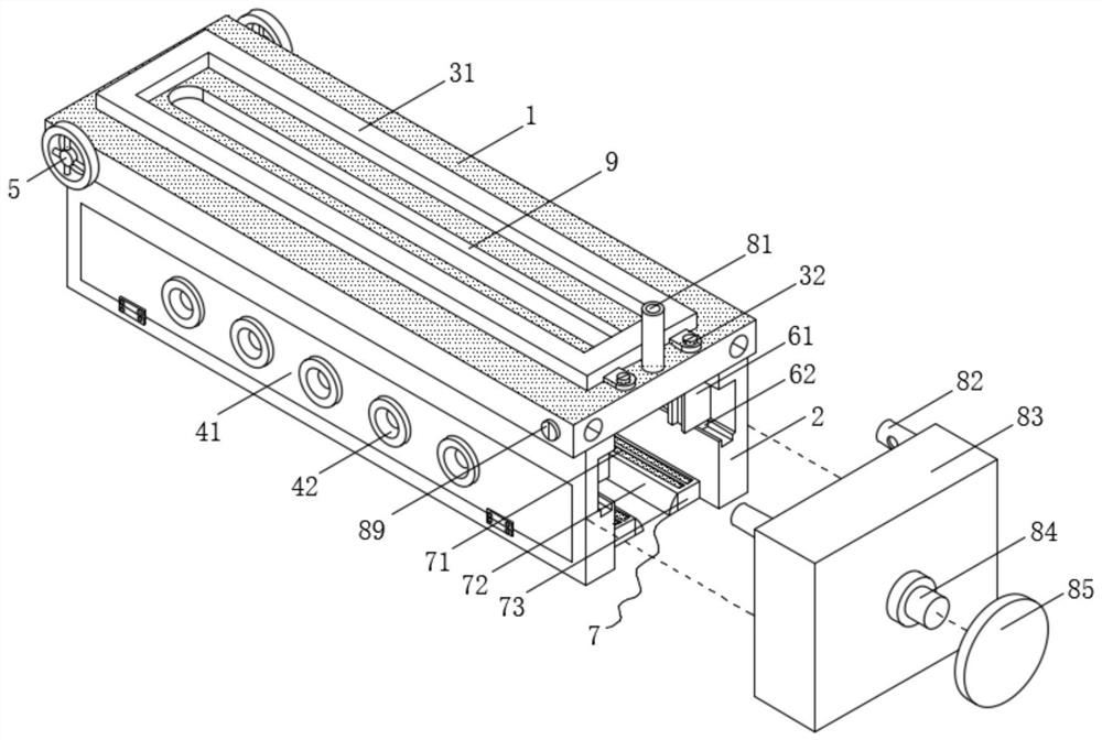
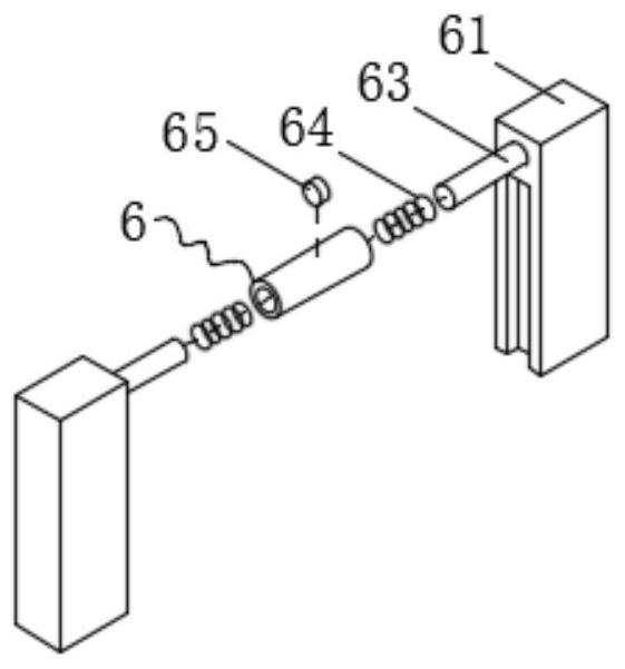
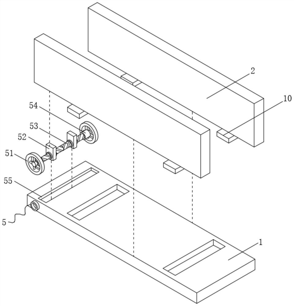
The invention discloses a lightweight design superposed beam stirrup inclination prevention device, and belongs to the technical field of superposed beams, the lightweight design superposed beam stirrup inclination prevention device comprises a top plate and side plates, an adjusting mechanism is arranged in the top plate, the side plates are arranged on the front side and the rear side of the lower surface of the top plate, and the lower surface of the adjusting mechanism is fixedly connected with the upper surfaces of the side plates; the opposite faces of the two side plates are each provided with a bearing mechanism and an anti-inclination mechanism, and the faces, away from each other, of the two side plates are each provided with a supporting mechanism. According to the device, the top plate and the side plates are arranged, the top plate and the side plates surround the superposed beam, the superposed beam is prevented from being exposed to the sun, meanwhile, the superposed beam can be protected against impact influences, the anti-inclination mechanisms can fix and protect the stirrups, and the situation that the stirrups are impacted, bent and inclined to affect use is avoided; and meanwhile, the supporting mechanism supports the superposed beam, friction between the bottom of the superposed beam and the carriage is avoided, and the protection effect on the superposed beam is further improved.

Description

technical field [0001] The invention belongs to the technical field of composite beams, in particular to a lightweight designed anti-tilt device for stirrups of composite beams. Background technique [0002] The composite beam is an assembled monolithic floor slab composed of prefabricated slabs and cast-in-place reinforced concrete layers. The laminated slab has good integrity and is suitable for high-rise buildings and large-bay buildings that require high overall rigidity. The laminated beam is a prefabricated panel. After the completion of the production, there will be a lot of stirrups on the surface for pouring Concrete fixed assembly. The composite beam needs to be transported to the construction site for assembly. During the transportation process, due to the factors of the transportation environment, the stirrup may be inclined. If the stirrup is inclined, it will affect the fixing effect of the concrete after pouring. At the same time It will affect the assembly f...

Claims


Application Information

Patent Timeline
IPC IPC(8): B65D88/12B65D88/74B65D90/00B65D90/08B60P7/08
Inventor 朱欢劼吴进华陆彬王聿暐周思埼卢耀武
Owner 常熟市博海新型建材有限公司
Learn More