
Electric motor coach

A technology for electric passenger cars and car bodies, applied in electric vehicles, electric power devices, vehicle energy storage, etc., to achieve the effect of simplifying the internal structure

Pending Publication Date: 2022-04-12
郑州深澜动力科技有限公司
View PDF1 Cites 0 Cited by
  • Summary
  • Abstract
  • Description
  • Claims
  • Application Information

AI Technical Summary

Problems solved by technology

[0003] The purpose of the present invention is to provide an electric passenger car to solve the technical problem in the prior art that the heat dissipation grille of the battery compartment is arranged on the side wall of the vehicle, which leads to the need to configure a heat dissipation fan

Method used


Image

  • Electric motor coach
  • Electric motor coach
  • Electric motor coach

Examples


specific Embodiment 1

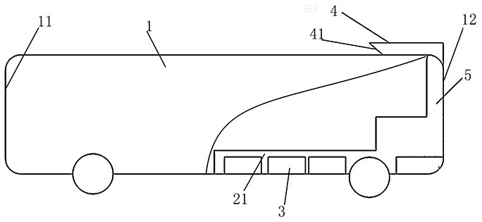
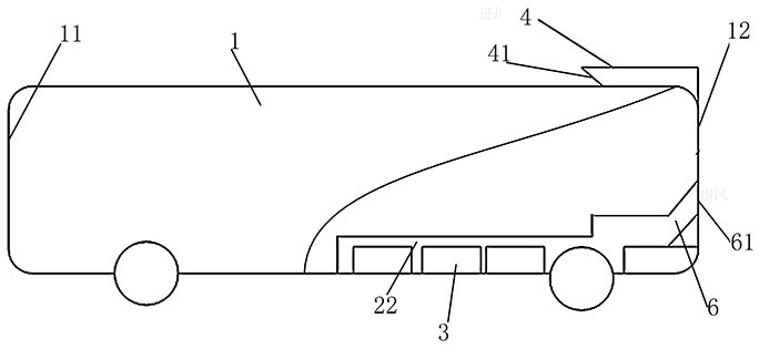
[0042] like Figure 1 to Figure 4 As shown, the electric bus includes a car body 1, the length of which extends along the front and rear directions. The front end of the car body 1 is a front end 11, and the rear end is a rear end 12. The left and right width directions are arranged, that is, the battery compartment 22 on the left side and the battery compartment 21 on the right side, such as image 3 As shown, a battery compartment partition 23 is set between the two battery compartments, but the two battery compartments are connected to each other, and the two battery compartments are arranged near the rear end of the vehicle body 1, and a battery pack 3 is fixed in each battery compartment, and the vehicle body 1 is provided with a heat dissipation channel for the battery compartment, which is used to introduce natural wind to cool the battery compartment.

[0043] In this embodiment, the heat dissipation channels of the battery compartment specifically include the air duc...

specific Embodiment 2

[0052] The difference between it and Embodiment 1 mainly lies in that in Embodiment 1, the air outlet is arranged on the rear side of the vehicle body. In this embodiment, the air outlet can also be arranged on the bottom surface of the vehicle body to form a form of heat dissipation that goes in and out from the top.

specific Embodiment 3

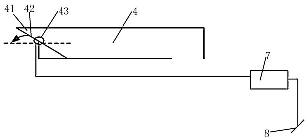
[0054] The main difference between it and Embodiment 1 is that in Embodiment 1, damper motors are respectively provided at the air outlet and the air inlet to control the closing of the corresponding dampers. In this embodiment, the air inlet damper may only be provided at the air inlet, and the air outlet damper may be omitted at the air outlet. At this time, care should be taken to arrange a ventilation grille at the air outlet to form a barrier.


PUM


Abstract

The invention relates to an electric motor coach which comprises a coach body, a battery compartment arranged at the bottom of the coach body, a battery pack arranged in the battery compartment, a battery compartment heat dissipation air duct arranged on the coach body and comprising a coach roof outer air duct and a coach body inner air duct, the coach roof outer air duct is provided with an air inlet arranged forwards and windward, and the coach body inner air duct comprises an air supply channel section and an air exhaust channel section. The air supply channel section is communicated with the car roof outer air channel and the battery compartment, one end of the air exhaust channel section is communicated with the battery compartment, the other end of the air exhaust channel section is communicated with an air outlet, and the air outlet is formed in the bottom face or the rear side face of the car body. When the passenger car runs forwards, natural air is injected into the air duct outside the car roof through the air inlet, enters the battery compartment through the air supply channel section and then is exhausted through the air exhaust channel section, so that heat dissipation and cooling of a battery pack in the battery compartment are realized. Due to the fact that the forward speed of the vehicle can guarantee that enough air enters the heat dissipation air channel of the battery compartment, a heat dissipation fan does not need to be arranged to drive air to flow, and the internal structure can be simplified.

Description

technical field [0001] The invention relates to an electric passenger car. Background technique [0002] With the gradual upgrading of the concept of green energy and environmental protection, most urban buses are driven by pure electricity, and generally adopt a distributed cabin design. To dissipate heat from the battery pack, the hatch grille is mostly arranged on the side of the vehicle body. For example, the heat dissipation structure for the power battery cabin of a passenger car disclosed in the Chinese utility model patent with the authorized announcement number CN201951221U. The rear wall is equipped with a rear wall air outlet. The air inlet and outlet of this battery compartment heat dissipation structure are arranged in a staggered manner, which cannot effectively utilize the convection heat dissipation formed by the vehicle and the surrounding air during driving. It is necessary to configure a cooling fan to achieve heat dissipation and cooling, which increases ...

Claims


Application Information

Patent Timeline
Patent Type & Authority Applications(China)
IPC IPC(8): B60K1/04B60L58/26
CPCY02T10/70
Inventor 吴二东马少华
Owner 郑州深澜动力科技有限公司
Learn More