
Automatic riveting equipment

An automatic riveting and equipment technology, applied in the field of workpiece riveting, can solve the problems of low work efficiency and high labor intensity, and achieve the effect of simple operation, low labor intensity and improved work efficiency

Pending Publication Date: 2022-04-12
广东省润杰服饰有限公司
View PDF5 Cites 2 Cited by
  • Summary
  • Abstract
  • Description
  • Claims
  • Application Information

AI Technical Summary

Problems solved by technology

[0004] In view of the related technologies mentioned above, the inventor believes that when the two parts to be riveted are riveted and fixed, the staff needs to manually place the two parts to be riveted in the stamping position of the riveting equipment, which is labor intensive and low in work efficiency.

Method used


Image

  • Automatic riveting equipment
  • Automatic riveting equipment
  • Automatic riveting equipment

Examples


Embodiment Construction

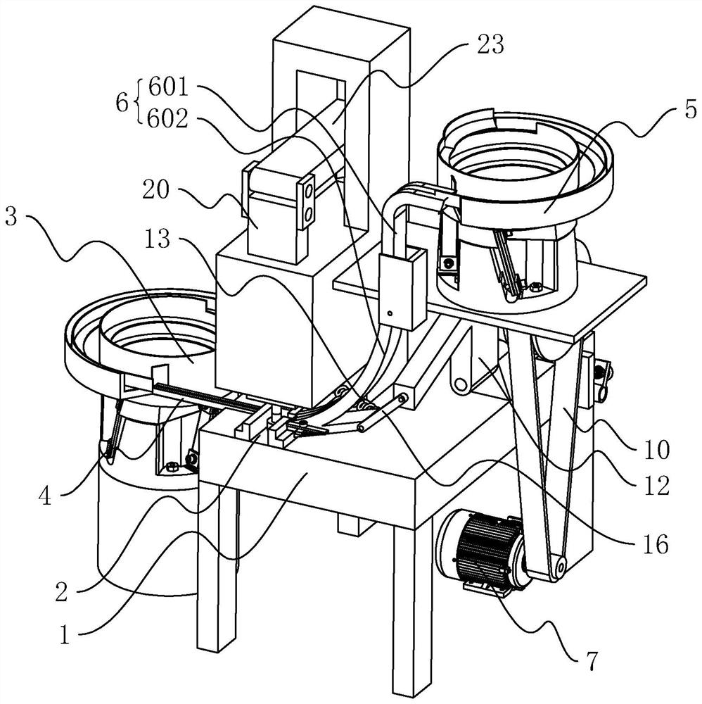
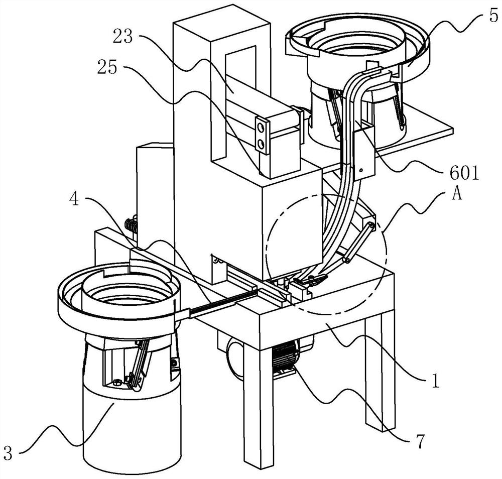
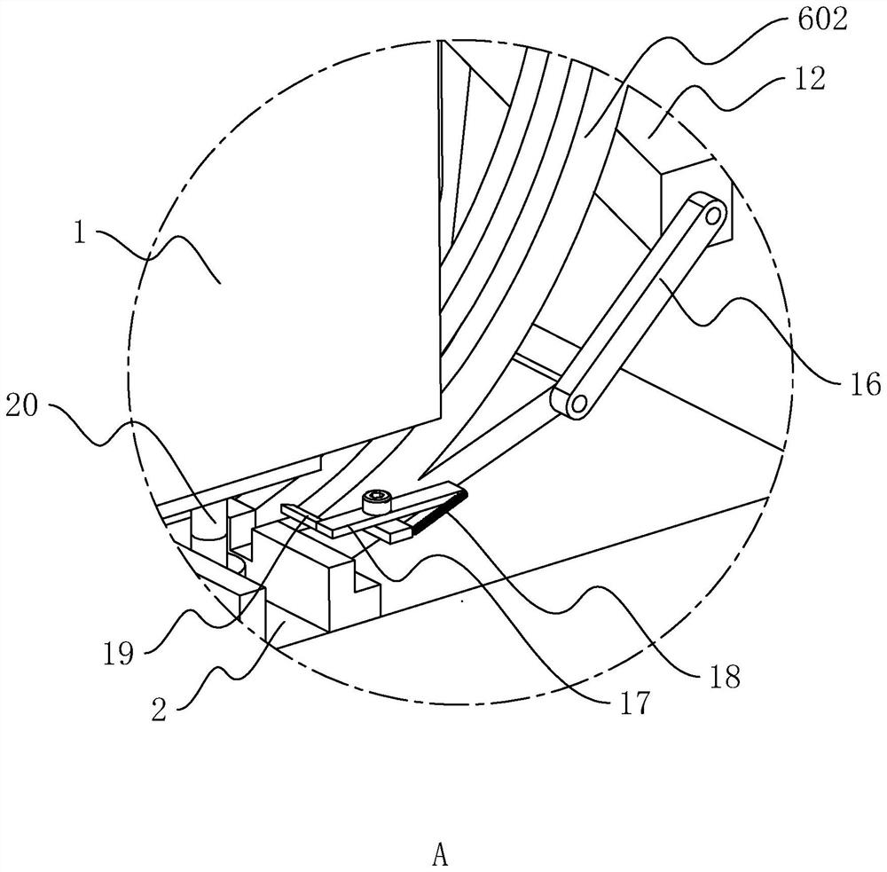
[0039] The following is attached Figure 1-6 The application is described in further detail.

[0040] The embodiment of the present application discloses an automatic riveting device. refer to figure 1 with figure 2 , the automatic riveting equipment includes a frame body 1, and the frame body 1 is provided with a material trough 2 arranged through the horizontal direction. Placement, the frame body 1 is also provided with a feeding mechanism, a pressing mechanism and a pushing mechanism.

[0041] refer to figure 2 with image 3 , the feeding mechanism includes a first feeding assembly and a second feeding assembly, the first feeding assembly includes a first feeding tray 3 and a first guide rail 4, the first feeding tray 3 is installed on the frame body 1, and the first guide rail One end of 4 is connected to the output end of the first feeding tray 3, and the other end of the first guide rail 4 is connected to the trough 2, so that the first guide rail 4 sends the ma...


PUM


Abstract

The invention discloses automatic riveting equipment, and belongs to the technical field of workpiece riveting, the automatic riveting equipment comprises a frame body, the frame body is provided with a feeding mechanism, a pressing mechanism and a pushing mechanism, the frame body is provided with a material placing groove for placing materials, the feeding mechanism comprises a first feeding assembly and a second feeding assembly, and the first feeding assembly is provided with a clamping mechanism; the first feeding assembly comprises a first feeding disc and a first guide rail. The second feeding assembly comprises a second feeding disc and a second guide rail. The material pressing mechanism comprises a material pressing piece and a material pressing movement assembly, the material pressing movement assembly is used for driving the material pressing piece to move in the vertical direction, the material pressing piece is located at the top of the material containing groove, the material pushing mechanism comprises a material pushing rod and a material pushing movement assembly, and the material pushing movement assembly is used for driving the material pushing rod to move in the horizontal direction. The material pushing rod is arranged in the material containing groove in a sliding mode in the horizontal direction. The riveting device has the advantages that two to-be-riveted parts can be conveniently placed at the stamping position of the riveting device, the labor intensity of workers is reduced, and the working efficiency is improved.

Description

technical field [0001] The invention relates to the field of workpiece riveting, in particular to an automatic riveting device. Background technique [0002] Riveting equipment is a commonly used equipment in the process of workpiece processing. It mainly realizes riveting between two workpieces through a stamping part moving in the vertical direction. [0003] The riveting equipment in the related art usually overlaps the two parts to be riveted and places them under the punching part of the riveting device, and then drives the punching part to move in the vertical direction to realize the riveting of the two parts to be riveted together and fixed. [0004] In view of the related technologies mentioned above, the inventor believes that when the two parts to be riveted are riveted and fixed, the staff need to manually place the two parts to be riveted in the stamping position of the riveting equipment, which is labor intensive and low in work efficiency. Contents of the i...

Claims


Application Information

Patent Timeline
Patent Type & Authority Applications(China)
IPC IPC(8): B21D39/00B21D43/04B21D45/02
Inventor 薛孝众
Owner 广东省润杰服饰有限公司
Learn More