
Locomotive cylinder cover cross arm guide rod installation precision detection system and method

A technology of installation accuracy and detection system, which is applied in the field of installation accuracy detection system of locomotive cylinder head transverse arm guide rod, which can solve the problems of heavy installation tools, low operation efficiency, and worker fatigue, so as to reduce operation risk factor and labor cost , the effect of improving inspection efficiency

Pending Publication Date: 2022-04-08
CRRC DALIAN CO LTD +1
View PDF0 Cites 0 Cited by
  • Summary
  • Abstract
  • Description
  • Claims
  • Application Information

AI Technical Summary

Problems solved by technology

[0006] 1. The detection method provided by the prior art requires workers to use detection tools for manual inspection, and the work efficiency is low
[0007] 2. The installation tools used are heavy, and long-term operations are likely to cause worker fatigue, which will affect the test results
[0008] 3. When using the existing technology for detection, there is no quantitative standard for the detection results, and it can only rely on the hand feeling of workers. The detection results of such detection methods often rely more on the skills and experience of individual workers, and occasional false detections (false detections, about to The unqualified inspection is more likely to be a qualified product)

Method used


Image

  • Locomotive cylinder cover cross arm guide rod installation precision detection system and method
  • Locomotive cylinder cover cross arm guide rod installation precision detection system and method
  • Locomotive cylinder cover cross arm guide rod installation precision detection system and method

Examples


Embodiment Construction

[0045] In order to make the purpose, technical solutions and advantages of the embodiments of the present invention clearer, the technical solutions in the embodiments of the present invention will be clearly and completely described below in conjunction with the drawings in the embodiments of the present invention. Obviously, the described embodiments It is a part of embodiments of the present invention, but not all embodiments. Based on the embodiments of the present invention, all other embodiments obtained by persons of ordinary skill in the art without making creative efforts belong to the protection scope of the present invention.

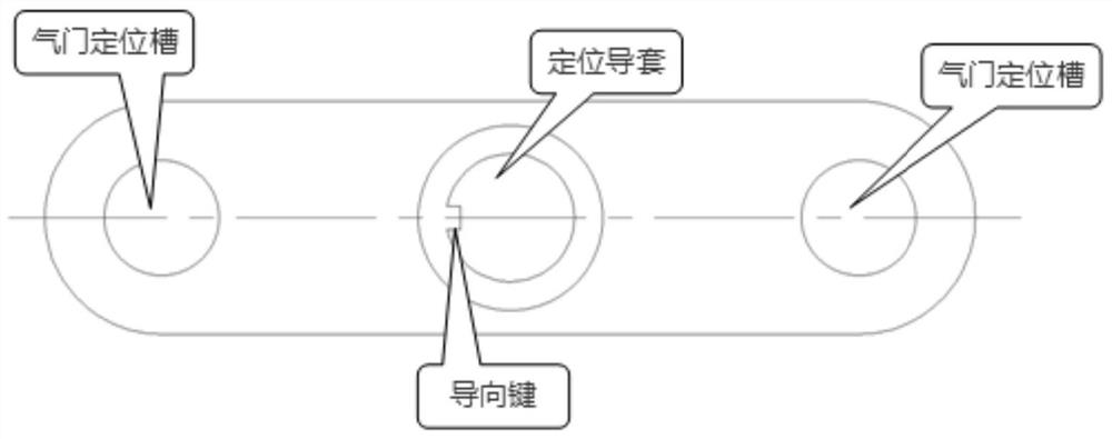
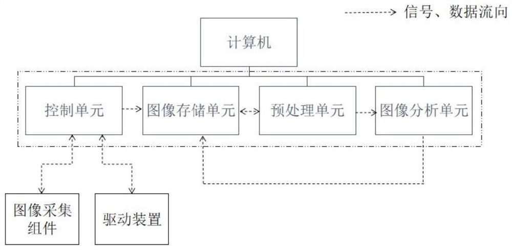
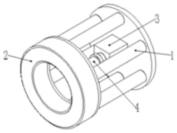
[0046] The embodiment of the invention discloses a locomotive cylinder head transverse arm guide rod installation accuracy detection system, including a positioning detection platform, an image acquisition system, a main control system and a driving device, the driving device is connected with the image acquisition system, and the main control...


PUM


Abstract

The invention provides a locomotive cylinder cover cross arm guide rod installation precision detection system and method. The device comprises a positioning detection platform, an image acquisition system, a main control system and a driving device, the driving device is connected with the image acquisition system, the main control system is connected with the image acquisition system and the driving device, and the positioning detection platform is used for placing a cylinder cover cross arm guide rod to be detected. The driving device is used for driving the image acquisition assembly to move to a position right above a cross arm guide rod of the cylinder cover to be detected under the control of the main control system, the image acquisition system is used for acquiring an original image and transmitting the original image to the main control system, and the main control system is used for carrying out preprocessing and feature extraction on the image; and judging whether the deflection angle of the cross arm guide rod key groove exceeds a qualified range or not based on a preset standard. According to the detection system, automatic detection is realized based on the computer and the image acquisition assembly, the detection efficiency is improved, and the false detection rate is greatly reduced; and meanwhile, the labor cost is reduced through an automatic detection mode.

Description

technical field [0001] The invention relates to the technical field of installing a cross-arm guide rod of a locomotive cylinder head, in particular to a system and method for detecting the installation accuracy of a cross-arm guide rod of a locomotive cylinder head. Background technique [0002] In the initial stage of engine technology development, dual-valve technology (single-inlet and single-row) is generally used. At this stage, the opening and closing of the valves are generally directly controlled by rocker arms (connecting rods), and each rocker arm (connecting rod) Can control a valve. With the development of science and technology, the continuous improvement of engine technology, and the requirements of environmental protection, multi-valve technology (multi-inlet and multi-row) has been produced. The emergence of multi-valve technology requires the rocker arm to be able to control two (or more) valves with the same name at the same time in terms of structure. At...

Claims


Application Information

Patent Timeline
Patent Type & Authority Applications(China)
IPC IPC(8): G06T1/00G06T7/00G06T7/62G06V10/25G06V10/34G06V10/141
Inventor 杨涛宋云鹏任佳才丛明鲍震刘磊王明悦
Owner CRRC DALIAN CO LTD
Learn More