Head fixing device based on surgical nursing
A fixing device and a technology for fixing the bottom, which are applied in the fields of heating appliances for treatment, cooling appliances for treatment, medical science, etc., and can solve the problems of inconvenient use of the head fixing device, uncomfortable fixing process, and poor fixing effect, etc. Problems, to achieve the effect of convenient surgical nursing operation, improve drug efficacy, and convenient clamping force
- Summary
- Abstract
- Description
- Claims
- Application Information
AI Technical Summary
Problems solved by technology
Method used
Image
Examples
Embodiment 1
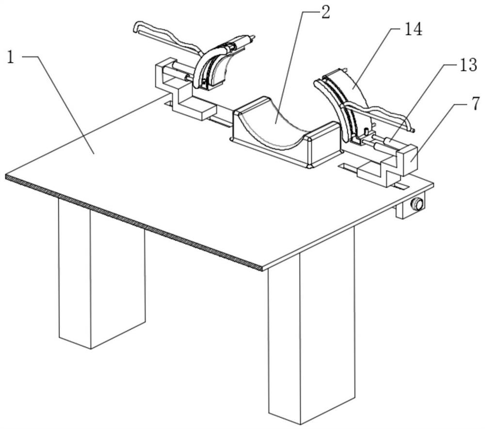
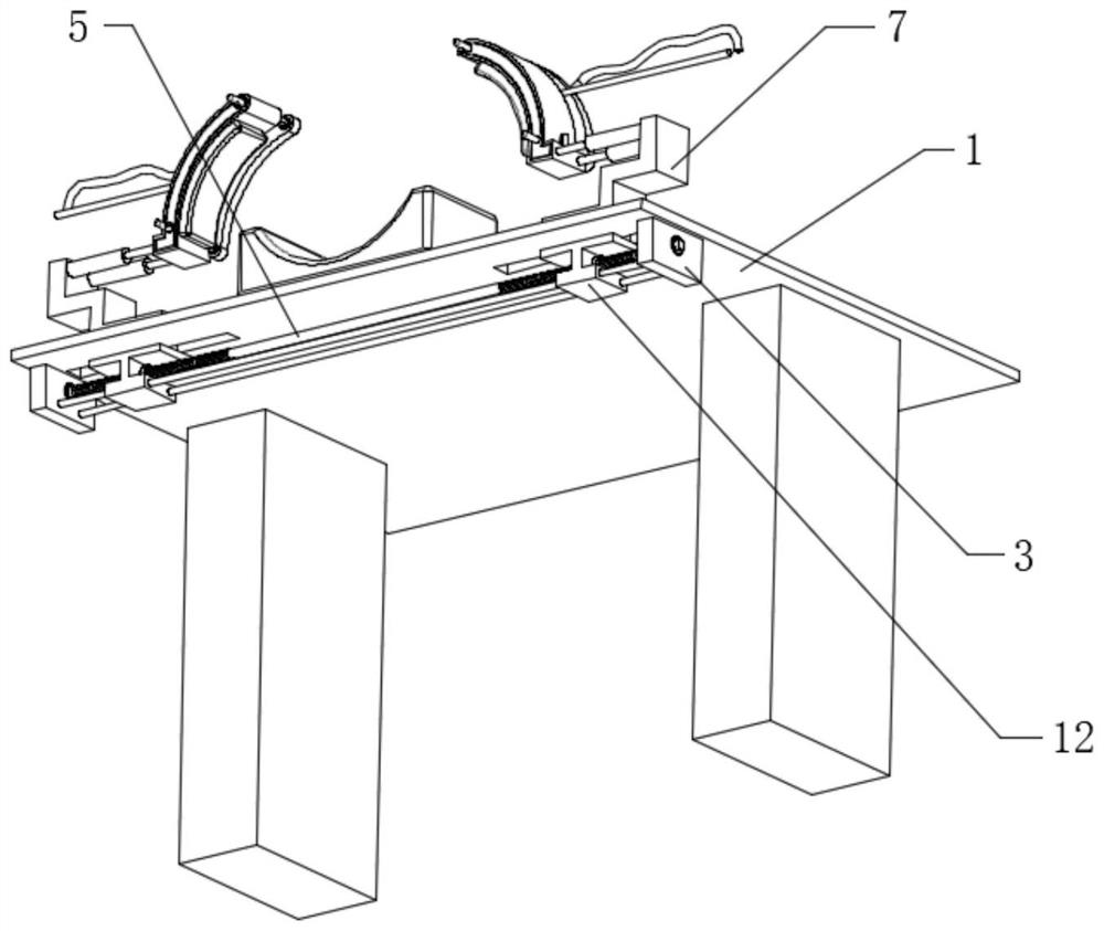
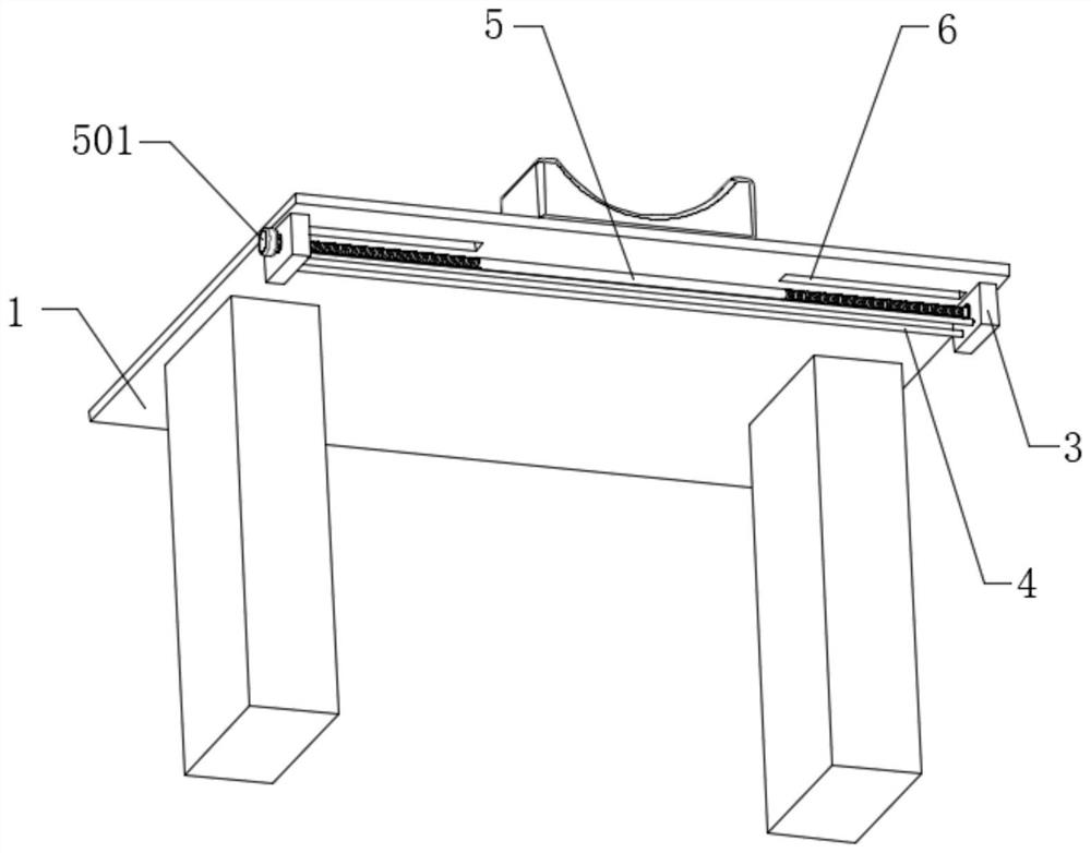
[0032] The embodiment of the present invention discloses a head fixation device based on surgical care, such as Figure 1-7 shown, including:
[0033] A surgical nursing bed 1, the top of the surgical nursing bed 1 is fixedly connected with a head pillow 2, and the bottom of the surgical nursing bed 1 is rotatably connected with a double-threaded screw rod 5;
[0034] Two groups of sliding arms 7, two groups of sliding arms 7 are slidably connected on the top of the surgical nursing bed 1, the bottom of the sliding arms 7 is provided with a nut seat 11, and the nut seat 11 is threadedly connected with the double thread screw rod 5, and the side of the sliding arm 7 A tight fitting mechanism 13 is fixedly connected to the wall;
[0035] The arc-shaped clamping seat 14, the arc-shaped clamping seat 14 is fixedly connected to the tight fitting mechanism 13, and the side wall of the arc-shaped clamping seat 14 is fixedly connected with an arc-shaped rubber elastic block 15, and t...
Embodiment 2
[0044] The embodiment of the present invention discloses a head fixation device based on surgical care, such as Figure 1-7 shown, including:
[0045] A surgical nursing bed 1, the top of the surgical nursing bed 1 is fixedly connected with a head pillow 2, and the bottom of the surgical nursing bed 1 is rotatably connected with a double-threaded screw rod 5;
[0046] Two groups of sliding arms 7, two groups of sliding arms 7 are slidably connected on the top of the surgical nursing bed 1, the bottom of the sliding arms 7 is provided with a nut seat 11, and the nut seat 11 is threadedly connected with the double thread screw rod 5, and the side of the sliding arm 7 A tight fitting mechanism 13 is fixedly connected to the wall;
[0047] The arc-shaped clamping seat 14, the arc-shaped clamping seat 14 is fixedly connected to the tight fitting mechanism 13, and the side wall of the arc-shaped clamping seat 14 is fixedly connected with an arc-shaped rubber elastic block 15, and t...
Embodiment 3
[0052] The embodiment of the present invention discloses a head fixation device based on surgical care, such as Figure 1-7 shown, including:
[0053] A surgical nursing bed 1, the top of the surgical nursing bed 1 is fixedly connected with a head pillow 2, and the bottom of the surgical nursing bed 1 is rotatably connected with a double-threaded screw rod 5;
[0054] Two groups of sliding arms 7, two groups of sliding arms 7 are slidably connected on the top of the surgical nursing bed 1, the bottom of the sliding arms 7 is provided with a nut seat 11, and the nut seat 11 is threadedly connected with the double thread screw rod 5, and the side of the sliding arm 7 A tight fitting mechanism 13 is fixedly connected to the wall;
[0055] The arc-shaped clamping seat 14, the arc-shaped clamping seat 14 is fixedly connected to the tight fitting mechanism 13, and the side wall of the arc-shaped clamping seat 14 is fixedly connected with an arc-shaped rubber elastic block 15, and t...
PUM
 Abstract
Description
Claims
Application Information
 - R&D Engineer
- R&D Manager
- IP Professional
- Industry Leading Data Capabilities
- Powerful AI technology
- Patent DNA Extraction
Browse by: Latest US Patents, China's latest patents, Technical Efficacy Thesaurus, Application Domain, Technology Topic, Popular Technical Reports.
© 2024 PatSnap. All rights reserved.Legal|Privacy policy|Modern Slavery Act Transparency Statement|Sitemap|About US| Contact US: help@patsnap.com


