A liquid metal-based hot-melt drill bit for vertical drilling of polar grain snow layers

A liquid metal and vertical drilling technology, which is applied in directional drilling, earthwork drilling, drilling equipment, etc., can solve the problems of uneven heating of the drill head, poor uniformity, and limitation of the length of the drilling tool, so as to reduce the probability of drill sticking and simplify the ground surface Equipment and the effect of saving drilling cost

Active Publication Date: 2022-08-09
JILIN UNIV
View PDF8 Cites 0 Cited by
  • Summary
  • Abstract
  • Description
  • Claims
  • Application Information

AI Technical Summary

Problems solved by technology

However, in the actual use process, due to the poor uniformity of the physical properties of the ice layer and the uneven heating of the drill head, there are differences in the melting speed of the various parts of the thermal melting drill bit, which often leads to deflection of the thermal melting drill hole, and the serious hole deviation can reach dozens. depth, resulting in the inability to accurately reach the target depth and formation
In order to realize the vertical drilling of ice layer thermal drilling, decompression drilling is usually adopted in the world, and the thermal melting drilling tool is suspended by cables to reduce the contact pressure between the drill bit and the ice layer, so that the drilling tool can return as much as possible under the action of gravity Vertical drilling axis, but this method is limited by the length of the drilling tool. For longer drilling tools, once the hole deviation occurs, it is almost impossible to correct it in a short distance

Method used


Image

  • A liquid metal-based hot-melt drill bit for vertical drilling of polar grain snow layers
  • A liquid metal-based hot-melt drill bit for vertical drilling of polar grain snow layers
  • A liquid metal-based hot-melt drill bit for vertical drilling of polar grain snow layers

Examples


Embodiment Construction

[0021] In order to illustrate the present invention more clearly, the present invention will be further described below with reference to the preferred embodiments and accompanying drawings. Those skilled in the art should understand that the content specifically described below is illustrative rather than restrictive, and should not limit the protection scope of the present invention. Unless otherwise defined, technical or scientific terms used herein should have the ordinary meaning as understood by one of ordinary skill in the art to which this invention belongs.

[0022] Well-known methods, procedures, procedures, components and circuits have not been described in detail in order to avoid obscuring the essence of the present invention.

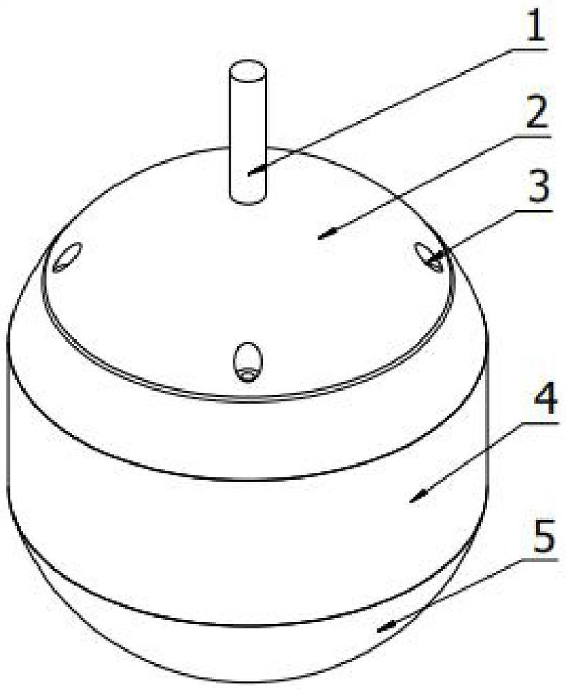
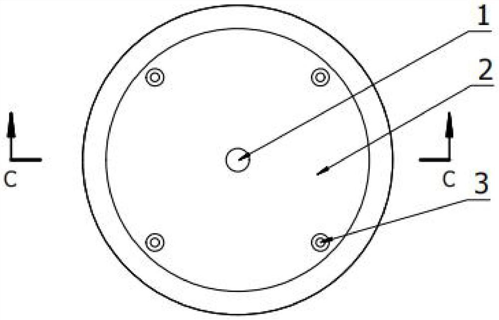
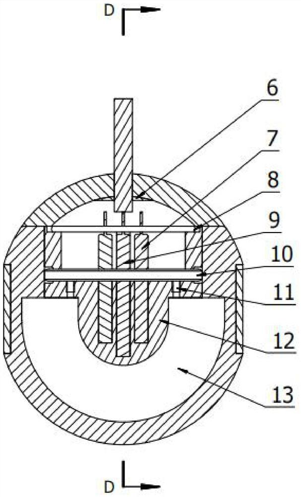
[0023] like figure 1 , figure 2 , image 3 and Figure 4 As shown in the figure, a liquid metal-based polar grain snow layer vertical drilling hot-melting drill bit includes a power supply cable 1, an upper cover 2, an insulating ring...


PUM


Abstract

The invention provides a liquid metal-based polar grain snow layer vertical drilling hot-melt drill bit, which belongs to the field of drilling equipment and includes a power supply cable, an upper cover, a heat insulating ring, a melting ice sphere, a short heating rod, a long heating rod, and a heating copper The core and the liquid metal cavity, the heating copper core and the melting ice sphere are concentrically arranged, and a high temperature resistant sealing ring is installed between them; the heating copper core, the melting ice sphere and the high temperature resistant sealing ring together form a liquid metal cavity, and the liquid metal cavity The liquid metal is filled with liquid metal, and the filling height of the liquid metal is less than the radius of the melting ice sphere; the liquid metal with high thermal conductivity is used as the heat transfer medium, and the fluidity and gravity of the liquid metal are used to realize the control of the heat transfer direction of the drill bit, so that the drill bit can be Automatically keep downward vertical drilling during drilling, which will greatly reduce the possibility of hole inclination in the polar snow layer hot melt drilling, improve the hit rate of the drilling target area, and reduce the risk of sticking of the drill bit during the drilling process. probability, has a wide range of application prospects.

Description

technical field [0001] The invention relates to the field of drilling tools, in particular to a liquid metal-based hot-melt drill bit for vertical drilling of polar grain snow layers. Background technique [0002] Ice layer thermal melting drilling is one of the drilling methods for rapid hole formation in polar snow and ice layers. It has the advantages of light equipment, easy portability and low power consumption. It has been widely used in polar and alpine glaciers in the past few decades. . Conventional electric heating hot-melt drills usually use heating rods or heating pipes to directly heat solid metal bodies or annular metal rings to achieve full-hole drilling or core drilling. However, in the actual use process, due to the poor uniformity of the physical properties of the ice layer and the uneven heating of the drill head, the ice melting speed of each part of the hot-melt drill bit is different, which often leads to the deflection of the hot-melt drilling hole, a...

Claims


Application Information

Patent Timeline
Patent Type & Authority Patents(China)
IPC IPC(8): E21B7/00E21B7/04E21B7/14
Inventor 范晓鹏李晨熠宫达张楠王如生武威
Owner JILIN UNIV
Why Eureka
Try Eureka