Multi-purpose top cover suction cup lifting appliance with adjustable lifting points
A multi-purpose, suction cup technology, applied in the field of spreaders, can solve the problems of spreaders without a positioning mechanism, affecting assembly efficiency and assembly quality, and the position of the spreader top cover is inconsistent, so as to ensure stability, improve the scope of application, and facilitate control balanced effect
- Summary
- Abstract
- Description
- Claims
- Application Information
AI Technical Summary
Problems solved by technology
Method used
Image
Examples
Embodiment 1
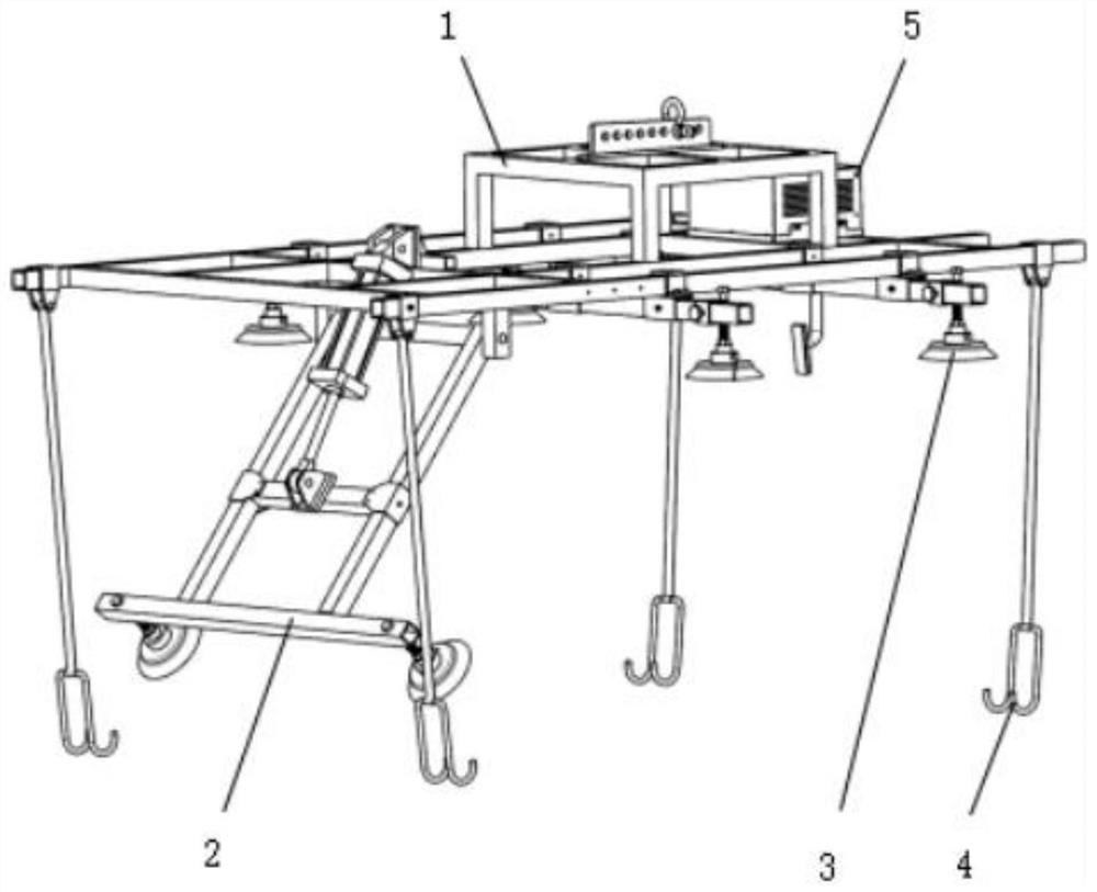
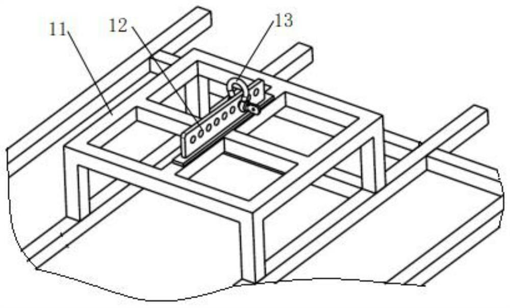
[0045] Such as figure 1 , 4 As shown in and 5, a multi-purpose ceiling suction cup spreader with adjustable lifting points includes a basic frame 1, and the basic frame 1 is connected with a rotation mechanism 2 and a translation mechanism.
[0046] The rotating mechanism 2 includes a rotating bracket 21 and a pushing assembly, the rotating bracket 21 is connected with a suction cup 3 , and the pushing assembly drives the rotating bracket 21 to rotate around the connection point between the rotating bracket 21 and the basic frame 1 .
[0047] The translation mechanism includes a beam 31 connected to the basic frame 1 , and the beam 31 is connected with a suction cup 3 .
[0048] By setting the rotation mechanism 2 and the translation mechanism, the position of the suction cup 3 can be adjusted according to different top covers, so as to adapt to different vehicle types and improve the scope of application of the spreader.
Embodiment 2
[0049] Embodiment 2, on the basis of Embodiment 1, the rotating mechanism 2 further includes a rotating shaft 22 , and the rotating bracket 21 is rotatably connected to the basic frame 1 through the rotating shaft 22 .
[0050] One end of the rotating bracket 21 is connected to the rotating shaft 22 , and the other end of the rotating bracket 21 is connected to a support rod 24 , and the support rod 24 is connected to a plurality of suction cups 3 .
[0051] The pushing component is an air cylinder 23 .
[0052] The pushing component can also be a hydraulic cylinder or other power components.
[0053] The cylinder body of the cylinder 23 is hinged to the basic frame 1 , and the cylinder rod of the cylinder 23 is hinged to the rotating bracket 21 .
[0054] During use, the rotating mechanism 2 is adjusted according to the shape of the top cover, so that the suction cup 3 on the rotating mechanism 2 can contact and absorb the top cover.
Embodiment 3
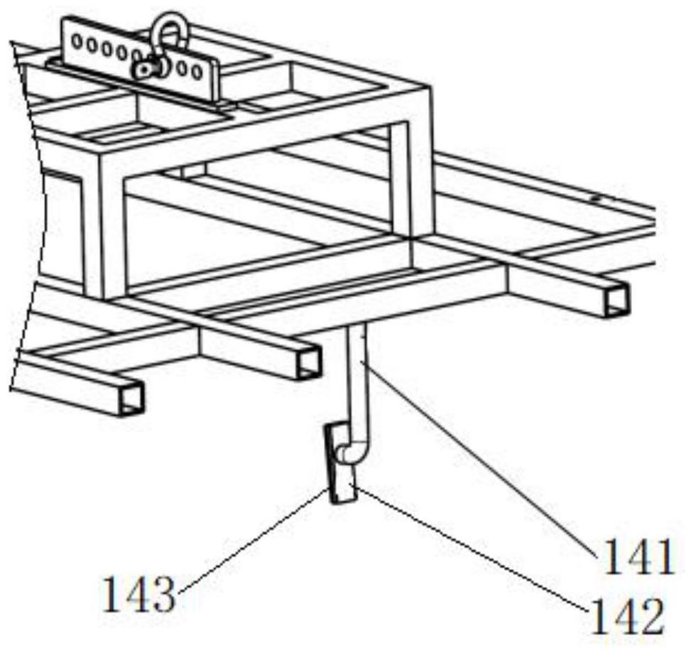
[0056] On the basis of Example 2, such as Figure 7 and 8 As shown, it also includes a plurality of protective mechanisms 4 connected to the basic framework 1, the protective mechanism 4 includes a protective rope mounting seat 41, a protective rope 42 and a hook 43, and one end of the protective rope 42 passes through the protective rope mounting seat 41 Hinged to the basic frame 1 , the other end of the protection rope 42 is connected with a hook 43 .
[0057] By setting the protection mechanism 4, when the suction cup 3 has a problem and the adsorption force is not strong, the protection mechanism 4 can support the top cover, preventing the top cover from falling and causing injury to employees.
[0058] During use, the suspension hook 43 is hooked on the lower end of the top cover to prevent the top cover from falling.
[0059] The protective rope mounting seat 41 includes a mounting base 411 connected to the basic framework 1, the mounting base 411 is connected with a p...
PUM
 Abstract
Description
Claims
Application Information
 - R&D
- Intellectual Property
- Life Sciences
- Materials
- Tech Scout
- Unparalleled Data Quality
- Higher Quality Content
- 60% Fewer Hallucinations
Browse by: Latest US Patents, China's latest patents, Technical Efficacy Thesaurus, Application Domain, Technology Topic, Popular Technical Reports.
© 2025 PatSnap. All rights reserved.Legal|Privacy policy|Modern Slavery Act Transparency Statement|Sitemap|About US| Contact US: help@patsnap.com


