
Flue gas purification equipment and flue gas purification method for steel plant

A flue gas purification and steel plant technology, applied in chemical instruments and methods, separation methods, cleaning methods and utensils, etc., can solve the problem of increasing the dust concentration in the filter space of the dust collector, aggravating the secondary back-mixing effect of dust, and increasing the filter bag filtration. Load and other problems, to achieve the effect of easy disassembly, cleaning and maintenance, reducing the impact of deformation, and improving the effect

Active Publication Date: 2022-04-01
中泓智能科技(河北)有限公司
View PDF10 Cites 0 Cited by
  • Summary
  • Abstract
  • Description
  • Claims
  • Application Information

AI Technical Summary

Problems solved by technology

When the bag filter adopts the air intake form of the ash hopper, the flue gas will impact and bring up the dust that has been deposited in the ash hopper, increase the dust concentration in the filter space of the dust collector, and intensify the secondary back-mixing of the dust. Increase the filter load of the filter bag, aggravate the erosion and wear of the filter bag, easy to damage and low service life
In addition, the bag filter can only intercept the particle dust but cannot remove the harmful gas in the flue gas, causing environmental pollution

Method used


Image

  • Flue gas purification equipment and flue gas purification method for steel plant
  • Flue gas purification equipment and flue gas purification method for steel plant
  • Flue gas purification equipment and flue gas purification method for steel plant

Examples


Embodiment Construction

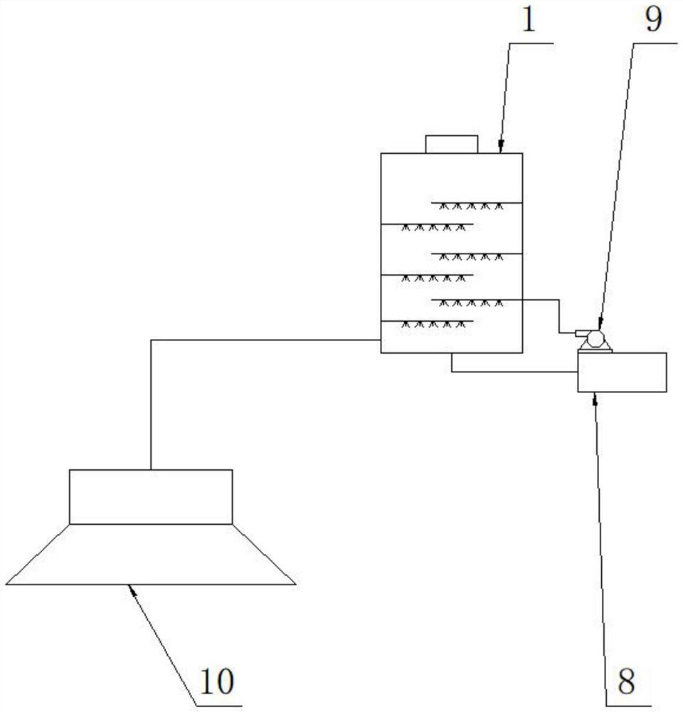
[0030] The core of the present invention is to provide a flue gas purification equipment and a flue gas purification method for iron and steel plants, which adopts a spraying method to carry out hot fume dust, remove dust and harmful gases, and improve the flue gas purification effect.

[0031] The technical solutions in the embodiments of the present invention will be clearly and completely described below in conjunction with the accompanying drawings in the embodiments of the present invention. Obviously, the described embodiments are only some of the embodiments of the present invention, not all of them. Based on the embodiments of the present invention, all other embodiments obtained by persons of ordinary skill in the art without making creative efforts belong to the protection scope of the present invention.

[0032] In describing the present invention, it should be understood that the terms "upper", "lower", "front", "rear", "left", "right", "top", "bottom", "inner", " ...


PUM


Abstract

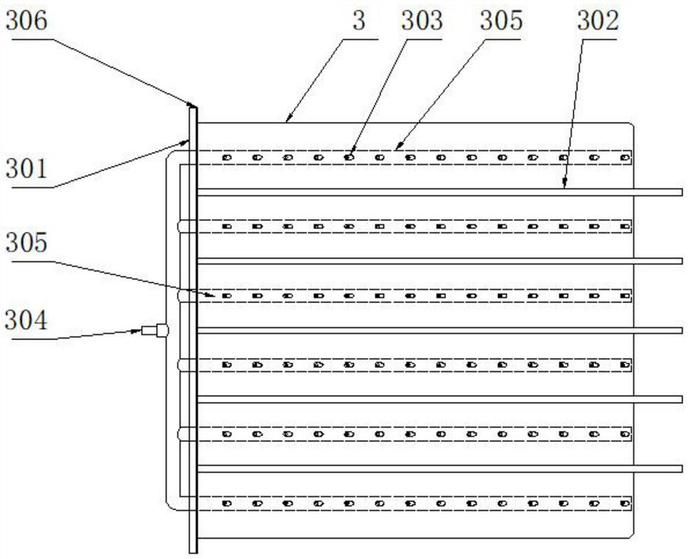
The invention discloses flue gas purification equipment for an iron and steel plant, which comprises an equipment main machine, a water tank, a water pump and a flue gas collecting cover, and is characterized in that the equipment main machine comprises an equipment main shell, a bracket, a plug-in mounting partition plate, a catalyst plate and an exhaust fan, and the equipment main shell is erected on the bracket; an inner cavity of the equipment main shell is divided into a reciprocating flue by a plurality of inserting partition plates of which the two sides are oppositely inserted in a staggered manner; a plurality of spray headers are arranged on a bottom plate of the plug-in mounting partition plate, and the water pipe connector is communicated to the spray headers through a pipeline; an air inlet and a water return pipe joint are arranged at the bottom of an inner cavity of the equipment main shell; a catalyst plate and an exhaust fan are arranged above the top inserting partition plate in the inner cavity of the equipment main shell; the flue gas collecting cover is communicated to the air inlet through an air pipe; after being filtered, the alkaline solution is pumped to each water pipe joint by the water pump. According to the flue gas purification equipment for the steel plant and the flue gas purification method, hot smoke dust is treated in a spraying mode, raised dust and harmful gas are removed, and the flue gas purification effect is improved.

Description

technical field [0001] The invention relates to the technical field of flue gas treatment in iron and steel plants, in particular to a flue gas purification device and a flue gas purification method for iron and steel plants. Background technique [0002] A large amount of high-temperature flue gas and smoke dust will be generated during the process of opening the blast furnace to tap iron, blocking the iron hole and flowing molten iron. In the casthouse, not only the flue gas emission is large, but the dust concentration in the post is high, and the high-temperature flue gas makes the smoke dust in a state of diffusion, which is easy to escape. Coupled with the high frequency and long time of blast furnace casting, a large area of ​​the casthouse is polluted by smoke dust, heat radiation, and harmful gases such as CO and SO2. The production and operating conditions are harsh and have a serious impact on the health of workers. At the same time, a large amount of smoke and d...

Claims


Application Information

Patent Timeline
Patent Type & Authority Applications(China)
IPC IPC(8): B01D50/40B01D53/75B01D53/78B01D53/50B01D53/86B01D53/62B01D53/26B08B15/02
Inventor 王松伟赵玉江张宇新
Owner 中泓智能科技(河北)有限公司
Learn More