
High-temperature and high-pressure clamp holder and using method thereof

A high temperature and high pressure, gripper technology, used in instruments, scientific instruments, measuring devices, etc., can solve the problems that the gripper is difficult to reach the temperature and pressure indicators, mechanical properties are reduced, and the sealing state is damaged, so as to avoid the danger of deflagration, The effect of improving pressure resistance and reducing the need for high temperature resistance

Pending Publication Date: 2022-03-29
QINGDAO SHIDA HUASONG SCI & TECH
View PDF0 Cites 0 Cited by
  • Summary
  • Abstract
  • Description
  • Claims
  • Application Information

AI Technical Summary

Problems solved by technology

At present, the temperature and pressure synchronization index generally achieved by the holder is 120°C-40MPa, which can meet the conventional simulation experiments. However, for some high-pressure and low-permeability cores, the formation environment cannot be effectively simulated, and the existing holder is difficult. Reach the temperature and pressure index of 180℃-70MPa
The main reasons include: 1. The nature of the fluororubber rubber cylinder is determined by its own nature. The fluororubber can be used for a long time in a non-pressurized state of 250 ° C, but the mechanical properties will be significantly reduced after pressure is applied, and shear tearing will occur, thereby destroying the sealing state. Seal failure under high pressure
2. The existing gripper plug and plunger are separate structures, and there will be a certain gap in the fit. This gap leads to shearing in high temperature and high pressure environments.

Method used


Image

  • High-temperature and high-pressure clamp holder and using method thereof
  • High-temperature and high-pressure clamp holder and using method thereof
  • High-temperature and high-pressure clamp holder and using method thereof

Examples


Embodiment Construction

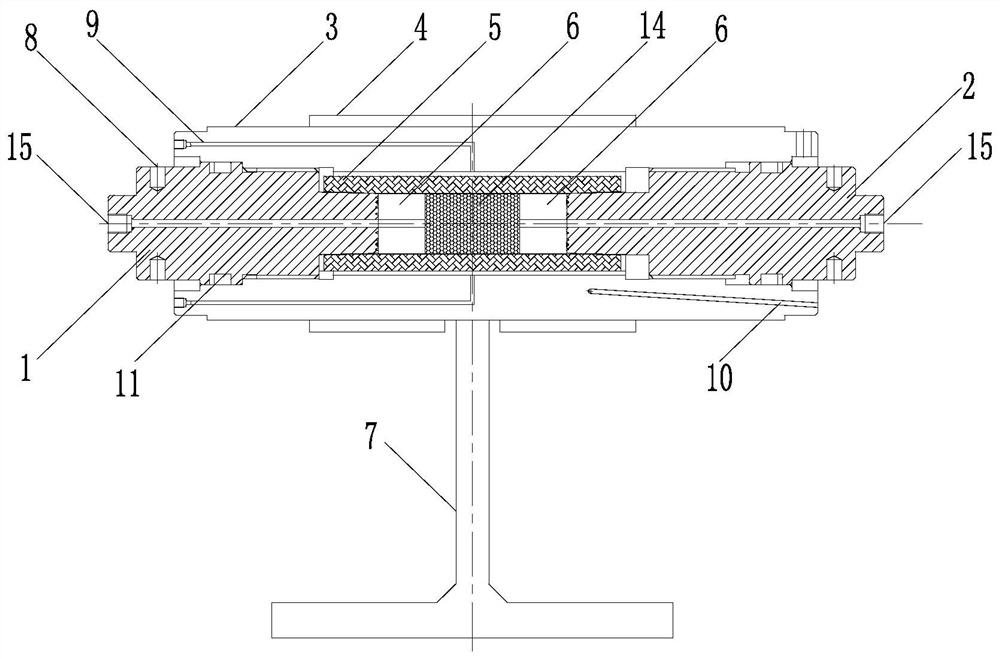
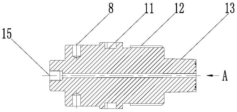
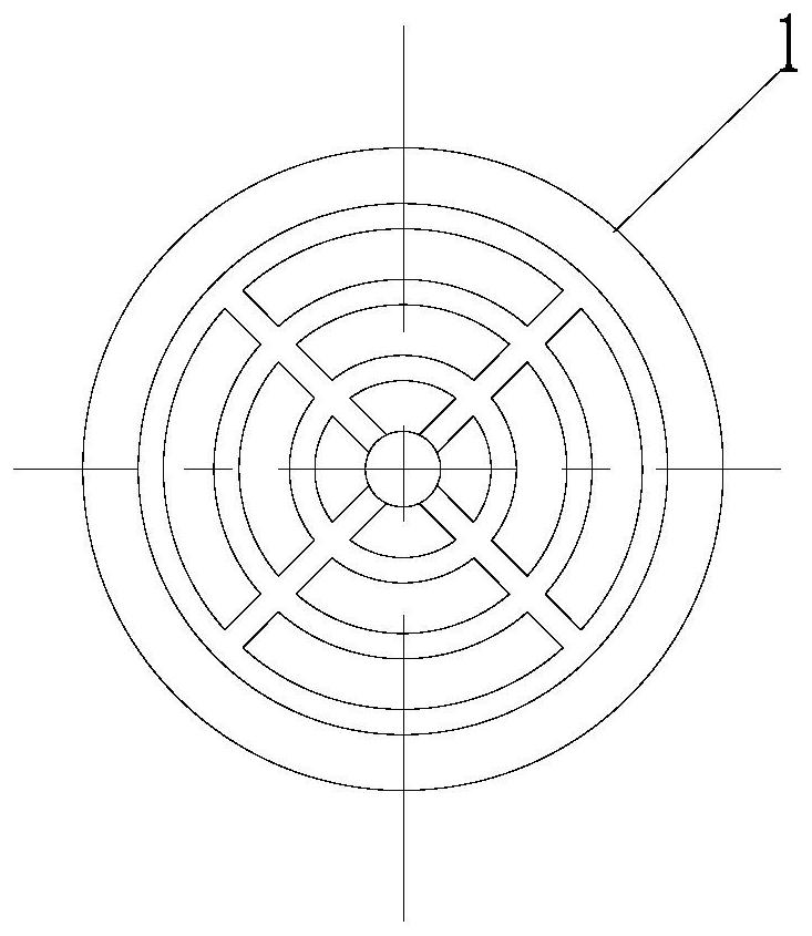
[0031] combine Figure 1 to Figure 5 As shown, the specific implementation of a high-temperature and high-pressure clamper provided by the present invention and its use method will be described.

[0032] A high-temperature and high-pressure clamper includes a first adjusting plug 1 , a second adjusting plug 2 , a cylinder body 3 , an electric heating jacket 4 , a rubber tube 5 , a spacer 6 and a bracket 7 . The first adjusting plug 1 and the second adjusting plug 2 are two identical adjusting plugs with an integrated structure, which are respectively assembled on both ends of the cylinder body 3 through threads, and the tapered plunger of the adjusting plug is inserted into the rubber tube , the sealing groove setting of the adjustment plug can meet the simulation conditions of high temperature and high pressure, and the high temperature and high pressure low permeability core seepage simulation test is carried out using this holder.

[0033] Wherein the rubber sleeve 5 is sl...


PUM


Abstract

The invention provides a high-temperature and high-pressure clamp holder and a use method thereof, relates to the technical field of clamping parts of testing devices, and can synchronously improve temperature and pressure indexes of the clamp holder. The holder comprises a first adjusting plug, a second adjusting plug, a barrel, an electric heating sleeve, a rubber sleeve, a cushion block and a support, the rubber sleeve is sleeved in the middle of the barrel, the first adjusting plug and the second adjusting plug are mounted at two ends of the barrel respectively, conical plungers of the adjusting plugs are inserted into the rubber sleeve, a rock core containing space is arranged in the middle of the rubber sleeve, and the cushion block is arranged in the rock core containing space. Cushion blocks are arranged at the two ends of the rock core containing space respectively; the bracket is connected with the cylinder body; a seepage through hole is formed in the adjusting plug along the axis, and a plurality of stress application holes are formed in the adjusting plug in the radial direction; the cylinder body is provided with an annular pressure loading channel which is communicated with the outer side of the rubber cylinder; and the side wall of the cylinder body is also provided with a temperature measuring hole. The structure eliminates the shearing force under the high-pressure condition, so that the pressure resistance of the rubber sleeve is improved, and the rubber sleeve is also suitable for tests in which flammable and explosive gas participates.

Description

technical field [0001] The invention relates to the technical field of clamping components of testing devices, in particular to a high-temperature and high-pressure clamp and a method for using the clamp. Background technique [0002] The holder is a device used to simulate formation conditions, put the core into the holder, use this device to effectively simulate the temperature and pressure of the bottom layer, and transmit the temperature and pressure to the core to simulate the temperature of the formation where the core is located and stress conditions. Using the entrances and exits set up upstream and downstream of the device, various displacement seepage tests can also be carried out on the core. At present, the temperature and pressure synchronization index generally achieved by the holder is 120°C-40MPa, which can meet the conventional simulation experiments. However, for some high-pressure and low-permeability cores, the formation environment cannot be effectively...

Claims


Application Information

Patent Timeline
IPC IPC(8): G01N15/08G01N13/00
CPCG01N15/082G01N13/00
Inventor 邵东亮宿连军谢长春谷勇王建强
Owner QINGDAO SHIDA HUASONG SCI & TECH
Learn More