Calibration control device, method and system
A technology of control equipment and control system, applied in the field of sensor calibration, can solve the problems of low sensor calibration efficiency and unfavorable industrial automation, and achieve the effect of improving calibration efficiency and realizing industrial automation.
- Summary
- Abstract
- Description
- Claims
- Application Information
AI Technical Summary
Problems solved by technology
Method used
Image

Examples
Embodiment 1
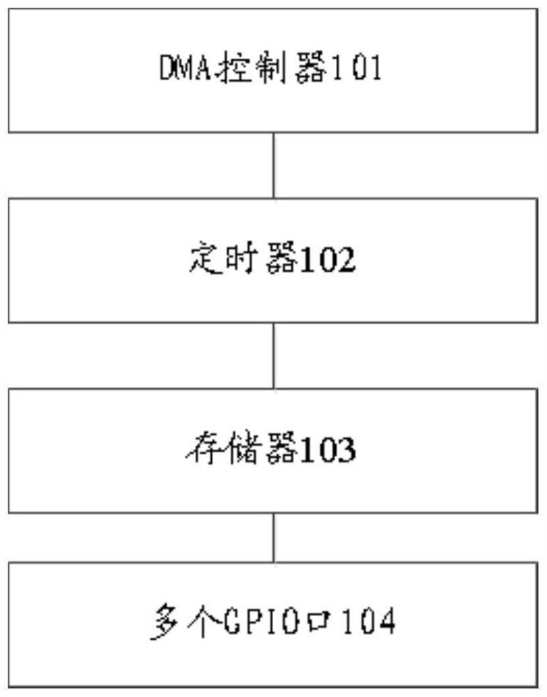
[0030] figure 1 It is a schematic structural diagram of a calibration control device provided by an embodiment of the present invention. Such as figure 1 Seen, this equipment comprises following structure: DMA controller 101, timer 102, memory 103 and a plurality of GPIO ports 104; Pre-stored in this memory 103 are used for testing the test data that the sensor to be demarcated; Set the first time interval for outputting data and the second time interval for reading data; the plurality of GPIO ports 104 are used to connect with at least one sensor to be calibrated of the peripheral; the DMA controller 101 is used for receiving When the first start command is reached, output the test data to the sensor to be calibrated through the plurality of GPIO ports 104 according to the first time interval, so as to process the test data through the sensor to be calibrated to obtain result data; the DMA control The device 101 is also used to read the result data from the sensor to be cal...
Embodiment 2
[0038] Figure 4 It is a schematic flowchart of a calibration control method provided by an embodiment of the present invention, and the method is applied to the above calibration control device. Depend on Figure 4 As seen, the method comprises the following steps;
[0039] Step S101: Receive the serial port command sent by the host computer.
[0040] Step S102: Perform single-line interface command interaction with the universal sensor interface of the peripheral sensor to be calibrated according to the serial port command, and realize the calibration of the sensor to be calibrated based on the preset sensor calibration program.
[0041] Step S103: Obtain the calibration result fed back by the sensor to be calibrated, and return a command response to the host computer through the serial port.
[0042] The calibration control method provided in this embodiment, the method includes: receiving the serial port command sent by the host computer; performing single-line interfac...
Embodiment 3
[0044] Figure 5 It is a schematic structural diagram of a calibration control system provided by an embodiment of the present invention. Depend on Figure 5 As can be seen, the system includes: a plurality of calibration control devices 501 in the above-mentioned embodiment 1, a host computer 503 and at least one switch 502; the calibration control device is connected to at least one sensor to be calibrated of multiple peripheral devices; It is used to receive the calibration command input by the user, and send the calibration command to multiple calibration control devices through the switch; the calibration control device is used to receive the calibration command issued by the host computer, and calibrate at least one sensor to be calibrated .
[0045] Wherein, the above-mentioned multiple calibration control devices 501 in the above-mentioned embodiment 1, at least one switch 502 and the host computer 503 are connected in sequence.
[0046] In this embodiment, when the...
PUM
 Abstract
Description
Claims
Application Information
 - R&D
- Intellectual Property
- Life Sciences
- Materials
- Tech Scout
- Unparalleled Data Quality
- Higher Quality Content
- 60% Fewer Hallucinations
Browse by: Latest US Patents, China's latest patents, Technical Efficacy Thesaurus, Application Domain, Technology Topic, Popular Technical Reports.
© 2025 PatSnap. All rights reserved.Legal|Privacy policy|Modern Slavery Act Transparency Statement|Sitemap|About US| Contact US: help@patsnap.com