Adjustable flow guide device
A diversion device and an adjustable technology, which is applied in exhaust gas devices, combustion product treatment, combustion methods, etc., can solve the problems of large flue resistance, inability to optimize the shape, elbow flue flow field distribution, etc., and achieve reduction Reduce operating costs, increase equipment utilization, and improve the effect of flow field distribution
- Summary
- Abstract
- Description
- Claims
- Application Information
AI Technical Summary
Problems solved by technology
Method used
Image
Examples
Embodiment 1
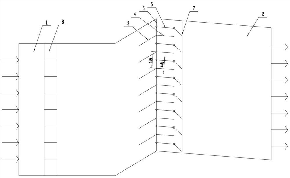
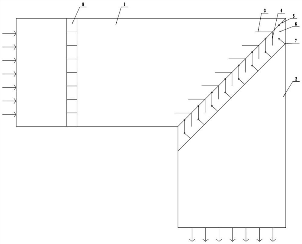
[0024] Please refer to figure 1 and figure 2 As shown, the present invention discloses an adjustable flow guiding device, which includes an air inlet flue 1 and an air outlet flue 2, and also includes a support rod 5 and a linkage mechanism 7, the air inlet flue 1 and the air outlet flue A plurality of first flow guide devices and a plurality of second flow guide devices are provided at the junction of the outlet flue 2, and the first flow guide devices and the second flow guide devices are arranged alternately along the radial direction of the flue, so The first guide device includes a connected front guide plate 3 and a rear guide plate 4, the support rod 5 is located at the tail end of the front guide plate 3 and slides radially through the flue, the second The deflector includes at least one intermediate deflector 6, one end of the intermediate deflector 6 is hinged to the support rod 5, and the other end is hinged to the linkage mechanism 7, and the linkage mechanism 7 ...
Embodiment 2
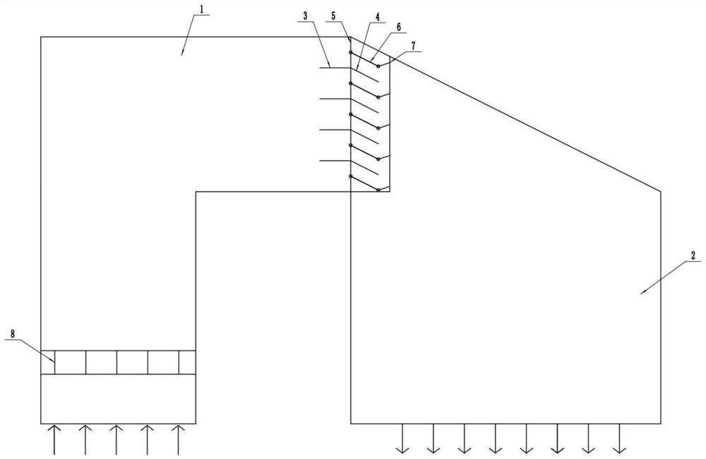
[0040] The difference from Embodiment 1 is that the joint of the inlet flue 1 and the outlet flue 2 is provided with a wedge-shaped elbow flue.
[0041] Please refer to image 3 As shown, an adjustable flow guiding device, the entrance of the outlet flue 2 is provided with a slope, the front deflector 3 is parallel to the intake flue 1, and the rear deflector 4 is parallel to the outlet flue 2 The slopes are parallel, the intake flue 1 extends into the outlet flue 2 for a certain distance, so that the two ends of the linkage mechanism 7 respectively penetrate the intake flue 1 and the slope, and the support rod 5 is located at the windward side of the front end of the linkage mechanism 7 , the middle deflector 6 is a straight deflector, one end of the straight deflector is hinged to the support rod 5, and the other end is hinged to the linkage mechanism 7.
Embodiment 3
[0043] The difference from Example 1 is that a circular elbow flue is provided at the junction of the inlet flue 1 and the outlet flue 2, and the middle deflector 6 includes an arc deflector 6-1 and a straight deflector 6. -2.
[0044] Please refer to Figure 4 As shown, an adjustable flow guide device, the junction of the inlet flue 1 and the outlet flue 2 is provided with a circular elbow flue, and the middle guide plate 6 includes an arc The deflector 6-1 and the straight section deflector 6-2, the junction of the arc deflector 6-1 and the straight section deflector 6-2 is provided with a support rod 5, and the straight section One end of the segment deflector 6-2 is hinged to the support rod 5, and the other end is hinged to the linkage mechanism 7. The arc deflector 6-1 is parallel to the circular elbow flue, so The straight section deflector is parallel to the outlet flue. The arc deflector 6-1 moves radially along the flue under the action of the support rod 5, and t...
PUM
 Abstract
Description
Claims
Application Information
 - R&D
- Intellectual Property
- Life Sciences
- Materials
- Tech Scout
- Unparalleled Data Quality
- Higher Quality Content
- 60% Fewer Hallucinations
Browse by: Latest US Patents, China's latest patents, Technical Efficacy Thesaurus, Application Domain, Technology Topic, Popular Technical Reports.
© 2025 PatSnap. All rights reserved.Legal|Privacy policy|Modern Slavery Act Transparency Statement|Sitemap|About US| Contact US: help@patsnap.com


