


Quick Research
Generate reliable direction feasibility study reports for your R&D in just a few steps.

Technical Q&A
Discover and master advanced knowledge NOW. Basics, ideas, possibilities, all at once.

Find Solutions
As an expert in R&D theories, this can generate solutions to your technical problems instantly.

Evaluate Feasibility
Analyze your overall solution with one click, know your potential R&D risks in advance.

Monitor Landscape
Get weekly tech updates, stay abreast of the latest tech innovations and key insights.
Pneumatic heliostat device
A heliostat and pneumatic technology, applied in the field of solar energy utilization, can solve the problems of high cost, high technical difficulty, inconvenient promotion, etc., and achieve the effect of low production cost and reduced complexity.
- Summary
- Abstract
- Description
- Claims
- Application Information
AI Technical Summary
Problems solved by technology
Method used
Image

Examples
Embodiment 1
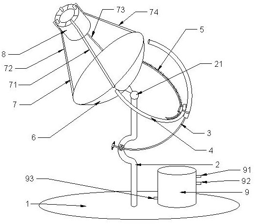
[0039] Embodiment one, with reference to figure 1 , a pneumatic heliostat device, comprising a horizontal base 1, wherein the horizontal base 1 is fixedly connected to the vertical column 2, the top of the vertical column 2 is provided with a universal ball hinge 21, and the upper end of the universal ball hinge 21 is connected to a butterfly mirror 6 One side of the bottom of the butterfly mirror 6 is fixedly connected to the horizontal telescopic tube 4, and the other side of the bottom of the butterfly mirror 6 is fixedly connected to the rack 5. The horizontal telescopic tube 4 is provided with an air motor 47, the gear of the air motor 47 and The rack 5 is meshed and connected, and the middle of the vertical column 2 is arranged in an arc shape. The arc portion of the vertical column 2 is fixedly connected to one end of the pitch telescopic tube 3, and the other end of the pitch telescopic tube 3 is connected to the horizontal direction telescopic tube. 4. Fixedly connect...
Embodiment 2
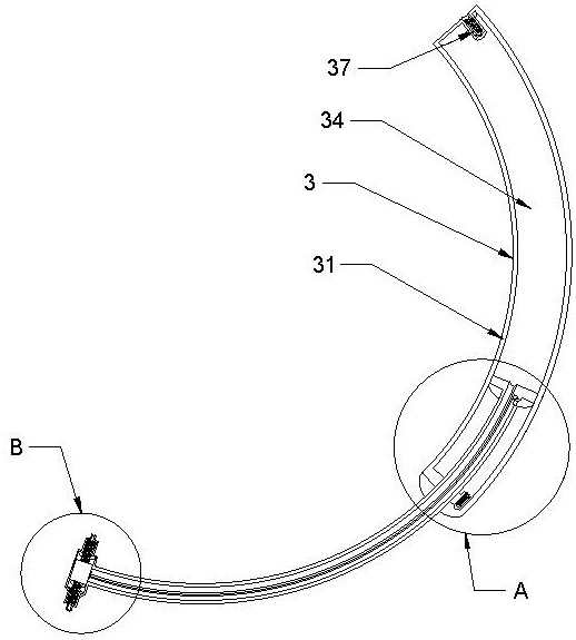
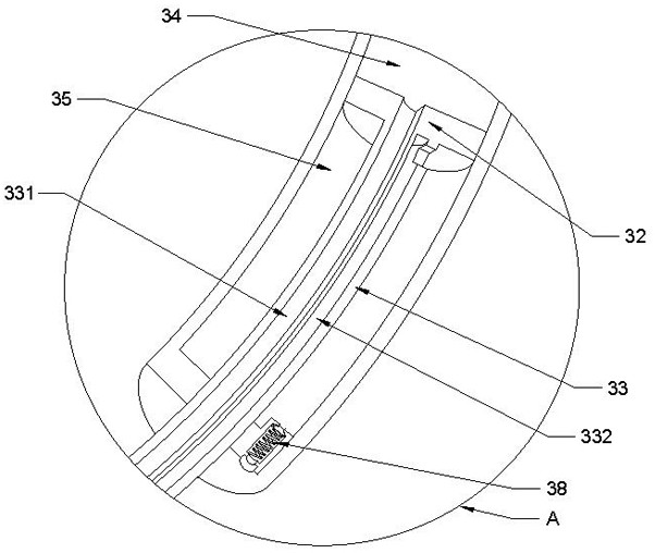
[0041] Embodiment two, refer to figure 2 , image 3 and Figure 4 , based on the basis of Embodiment 1, the pitch telescopic tube 3 includes an arc-shaped tube body 31, which is slidably connected to a piston 32 in the arc-shaped tube body 31, and the piston 32 is fixedly connected to an arc-shaped hollow piston rod 33, and the arc-shaped hollow piston The rod 33 is slidingly connected to the arc-shaped pipe body 31, and the arc-shaped hollow piston rod 33 is provided with a first air passage 331 and a second air passage 332. The first air passage 331 communicates with the upper cavity 34 of the pipe, and the second air passage 332 communicates with the lower tube cavity 35, and the other end of the arc-shaped hollow piston rod 33 is connected to the air pressure control reversing valve 36. , the pipe body 362 is connected with the first sliding column 361 by a compression spring, the pipe body 361 is provided with a limit groove up and down, the middle of the pipe body 362...
Embodiment 3
[0043] Embodiment three, refer to Figure 5 and Figure 7 , on the basis of Embodiment 1, the telescopic tube 4 in the horizontal direction includes a storage tube 411, the first sleeve tube 412 is slidably connected in the storage tube 411, the second sleeve tube 413 is slidably connected in the first sleeve tube 412, and the second sleeve tube 413 is slidably connected to the second sleeve tube 413 is slidingly connected to the third casing 414, and the other end of the third casing 414 is fixedly connected to the hollow pipe 42. The side of the hollow pipe 42 is provided with an air motor 47, and the bottom of the hollow pipe 42 is provided with an air motor intake valve 44 and a two-way storage. Can switch 45.
[0044] In this embodiment, the sleeves, storage tubes, and hollow tubes are arc tubes with the universal ball hinge 21 as the center of the circle, and the arc lengths are equal, and the corresponding arc is π / 3, and the third sleeve 414 is fixed Connect the holl...
PUM
 Abstract
Description
Claims
Application Information
 - R&D Engineer
- R&D Manager
- IP Professional
- Industry Leading Data Capabilities
- Powerful AI technology
- Patent DNA Extraction
Browse by: Latest US Patents, China's latest patents, Technical Efficacy Thesaurus, Application Domain, Technology Topic, Popular Technical Reports.
© 2024 PatSnap. All rights reserved.Legal|Privacy policy|Modern Slavery Act Transparency Statement|Sitemap|About US| Contact US: help@patsnap.com