Inductive brushless motor function detection system, method and controller

A motor controller and function detection technology, applied in the direction of single motor speed/torque control, electronic commutator, etc., can solve the problems of single board function inspection, controller production unit can not be realized, etc., to reduce production time cost, The effect of controllable production quality and improving test efficiency

Pending Publication Date: 2022-03-25
GREE ELECTRIC APPLIANCES INC
View PDF0 Cites 0 Cited by
  • Summary
  • Abstract
  • Description
  • Claims
  • Application Information

AI Technical Summary

Problems solved by technology

[0002] With the increasing requirements of social energy efficiency upgrades, brushless DC motors have high energy efficiency and are widely used. In order to ensure the reliability of motor startup and operation, a sensor solution is usually used. The motor controller of this solution needs to detect the position signal of the motor rotor (magnetic field) to Normal operation, so to check the functional integrity of the motor driver, it must be installed inside the motor before the test can be carried out, resulting in the failure of the controller production unit to realize the single board function test;

Method used


Image

  • Inductive brushless motor function detection system, method and controller
  • Inductive brushless motor function detection system, method and controller
  • Inductive brushless motor function detection system, method and controller

Examples


Embodiment 1

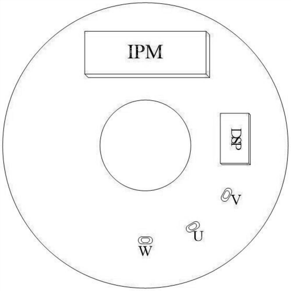
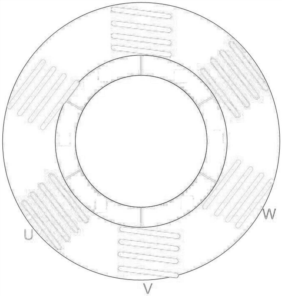
[0024] according to figure 1 , 2 , 3, the present embodiment proposes a sensory brushless motor function detection system, including a motor controller, a rotating magnetic field generator and a motor body, the control board of the motor controller is provided with a main control chip, a power The device IPM and the position sensor elements U, V, W; the motor body is provided with a stator coil, and the stator coil is a three-phase coil U, V, W;

[0025] The motor controller is connected with three-phase coils U, V, W, and the position sensor elements U, V, W are all provided with inductance coils.

[0026] The motor controller is connected with three-phase coils U, V, W.

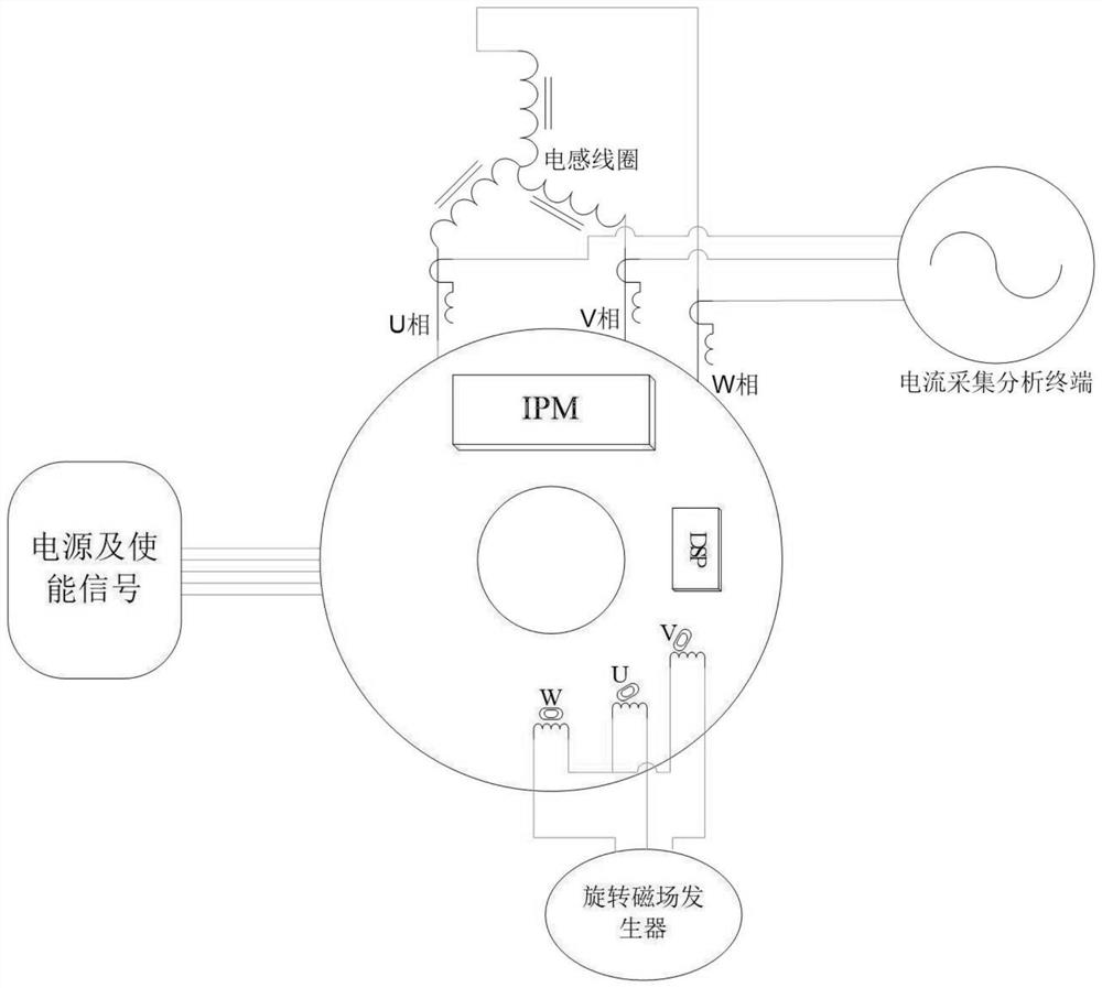
[0027] The inductance coil is driven by a rotating magnetic field generator, and the rotating magnetic field generator is realized by a non-inductive FOC motor driving board or a square wave motor driving board or a stepping motor square wave driving board.

[0028] The motor controller is driven by a po...

Embodiment 2

[0031] according to figure 1 , 2 , 3, this embodiment proposes a sensory brushless motor function detection method, applied to the motor controller, including the following steps:

[0032] Use the rotating magnetic field generator to drive the inductance coils under the position sensor elements U, V, and W to generate three fixed magnetic fields with different strengths; the position sensor elements U, V, and W sense the static position information of the inductance coil magnetic field to provide motor control The main control chip obtains the enabling signal and the static position information of the magnetic field (inductance simulation), and then outputs the SVPWM wave to the power device IPM through algorithm operation, driving the three-phase coil U, V, W; using the rotating magnetic field generator Continuously change the current of the inductor coil to realize the change of the magnetic field strength, and simulate the change of the magnetic field strength when the rot...

Embodiment 3

[0035] This embodiment proposes a sensory brushless motor function detection controller, including a computer-readable storage medium storing a computer program and a processor, and when the computer program is read and run by the processor, the described A method for detecting the function of a sensory brushless motor.


PUM


Abstract

The invention provides an inductive brushless motor function detection system and method and a controller, and relates to the technical field of motors, the inductive brushless motor function detection system comprises a motor controller, a rotating magnetic field generator and a motor body, a control panel of the motor controller is provided with a main control chip, a power device IPM and position sensor elements U, V and W; a stator coil is arranged in the motor body, and the stator coil is a three-phase coil U, a three-phase coil V and a three-phase coil W; according to the invention, the rotating magnetic field generator is adopted to drive the three inductance coils to generate magnetic field changes so as to simulate a changing rotating magnetic field generated when the motor rotor rotates inside, alternating three-phase current is output by detecting the changing magnetic field to drive the three-phase coils, and the function test of the motor controller can be realized by collecting and analyzing the output three-phase current data. By driving the three inductance coils, the operation condition of the rotor in the motor can be simulated, and the function test of the motor controller single body can be realized without installing the rotor.

Description

technical field [0001] The invention relates to the field of motor technology, in particular to a sensory brushless motor function detection system, method and controller. Background technique [0002] With the increasing requirements of social energy efficiency upgrading, brushless DC motors have high energy efficiency and are widely used. In order to ensure the reliability of motor startup and operation, a sensor solution is usually used. The motor controller of this solution needs to detect the position signal of the motor rotor (magnetic field) to Normal operation, so to check the functional integrity of the motor driver, it must be installed inside the motor before the test can be carried out, resulting in the failure of the controller production unit to realize the single board function test; [0003] In order to improve the production efficiency of the motor controller and ensure the production quality, it is necessary to develop a sensory motor controller single boar...

Claims


Application Information

Patent Timeline
Patent Type & Authority Applications(China)
IPC IPC(8): H02P6/08H02P6/16
CPCH02P6/08H02P6/16
Inventor 梁冠权李祖光曹伟杰陈海潮汪峰
Owner GREE ELECTRIC APPLIANCES INC
Why Eureka
Try Eureka