Balanced current output control method of virtual synchronous machine under unbalanced voltage condition

A technology of virtual synchronous machine and balancing voltage, which is applied in the direction of AC network voltage adjustment, single-network parallel feeding arrangement, and multi-phase network asymmetry reduction, etc. To achieve the effect of simple structure, wide application range and increased stability

Active Publication Date: 2022-03-25
SOUTHWEST JIAOTONG UNIV
View PDF10 Cites 0 Cited by
  • Summary
  • Abstract
  • Description
  • Claims
  • Application Information

AI Technical Summary

Problems solved by technology

[0004]2. The conversion of voltage and current commands in the current loop needs to obtain the impedance parameters of the transmission line in advance, and the line impedance is difficult to obtain in practice
In addition, the line impedance will change with the external factors of time and weather. If the line impedance is measured in advance and then brought in with a fixed value, the control accuracy will decrease due to errors;
[0005]3. This technology needs to convert the original signal to the dq coordinate system through coordinate transformation, the operation is complex, and the controller has high requirements for computing power
The introduction of virtual impedance requires coordinate transformation or differential calculation, which requires a large amount of calculation
[0008]2. The larger the virtual impedance, the better the effect of suppressing negative sequence current, but if the virtual impedance is too large, the equivalent line impedance will be larger, which will cause instability. are contradictory
Due to the huge phase change of the proportional resonance controller at the resonance point, errors will inevitably occur in actual use, and the control accuracy is not high

Method used


Image

  • Balanced current output control method of virtual synchronous machine under unbalanced voltage condition
  • Balanced current output control method of virtual synchronous machine under unbalanced voltage condition
  • Balanced current output control method of virtual synchronous machine under unbalanced voltage condition

Examples


Embodiment

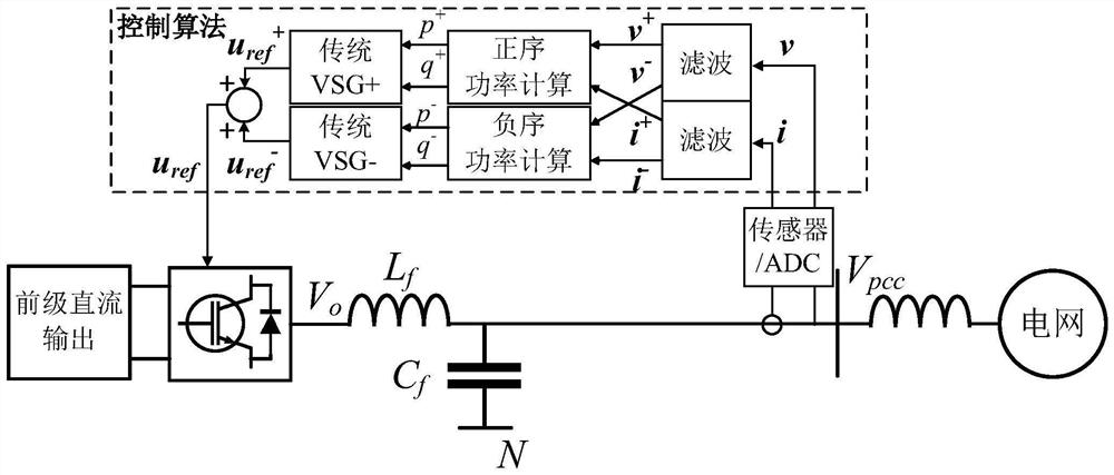
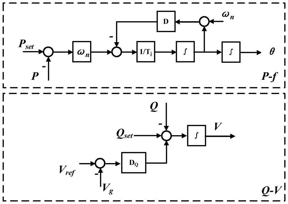
[0061] figure 1 It is a main circuit and a control block diagram of the present invention, illustrating that the present invention is a control method based on a three-phase grid-connected inverter. figure 2 It is the control block diagram of the traditional virtual synchronous machine utilized by the present invention, and it is the figure 1 A supplementary description of the control structure in .

[0062] The overall process includes the following steps:

[0063] Step 1. Sampling the three-phase voltage v=[v a v b v c ] T and three-phase current i=[i a i b i c ] T , the obtained analog signal is converted into digital signal by ADC and sent to the microprocessor (MCU).

[0064] exist figure 1 In the embodiment, it is represented by the module "Sensor / ADC". This module represents three sets of voltage sensors and three sets of current sensors. The sensors need to be isolated, and signals including but not limited to Hall sensors can be used for signal acquisi...


PUM


Abstract

The invention provides a virtual synchronous machine balance current output control method under an unbalanced voltage condition, which comprises the following steps of: 1, sampling voltage and current of an output end of a virtual synchronous machine, and extracting positive and negative sequence components through a filter; 2, calculating the extracted positive and negative sequence voltage and current to obtain instantaneous positive and negative sequence active and reactive power; 3, performing decoupling control on positive and negative sequence power; and 4, superposing the output voltage instructions of the positive and negative sequence conventional virtual synchronous machines, and outputting an inverter gate signal through SPWM modulation. According to the invention, the control structure of the virtual synchronous machine is improved, so that the virtual synchronous machine can work normally under an unbalanced power grid.

Description

technical field [0001] The invention belongs to the technical field of electric power control, and in particular relates to a method for controlling the balanced current output of a virtual synchronous machine under unbalanced voltage conditions. Background technique [0002] CN105098804B The invention discloses a control method and device for a three-phase unbalanced current of a virtual synchronous generator, wherein the method includes the following steps: establishing a VSG rotor motion equation and a VSG virtual excitation equation; decomposing the unbalanced grid voltage into positive Sequence, negative sequence, zero sequence voltage and corresponding phase sequence current, to analyze the unbalance problem encountered by decomposing the active power and reactive power output by VSG; calculate the reference command of dq axis current according to the output three-phase voltage signal; The current reference command is converted into a PWM voltage modulation signal thro...

Claims


Application Information

Patent Timeline
Patent Type & Authority Applications(China)
IPC IPC(8): H02J3/38H02J3/26H02J3/40H02J3/16
CPCH02J3/38H02J3/26H02J3/40H02J3/16Y02E40/30Y02E40/50
Inventor 石章海阮锦浩王仕松
Owner SOUTHWEST JIAOTONG UNIV
Why Eureka
Try Eureka