Wire moving and overturning mechanism of solar panel wire welding machine

A solar panel and flip mechanism technology, applied in welding equipment, semiconductor devices, auxiliary devices, etc., can solve the problems of inability to meet actual use requirements, complex control systems, unfavorable production and use, etc., to shorten the movement time, improve the operation accuracy, The effect of improving work efficiency

Pending Publication Date: 2022-03-25
吴辉辉
View PDF1 Cites 0 Cited by
  • Summary
  • Abstract
  • Description
  • Claims
  • Application Information

AI Technical Summary

Problems solved by technology

[0003] When the above-mentioned patented wire-taking mechanism is working, it needs to perform multiple actions such as moving, telescopic, rotating, and clamping. Each action requires at least one motor to control and is equipped with multiple sensors. The control system is complicated and the failure rate is high. , and it is not easy to maintain. During the working process of automation equipment, it is easy to break down, which is not conducive to actual production and use. The above patents cannot meet the actual use needs to a certain extent.

Method used


Image

  • Wire moving and overturning mechanism of solar panel wire welding machine
  • Wire moving and overturning mechanism of solar panel wire welding machine
  • Wire moving and overturning mechanism of solar panel wire welding machine

Examples


Embodiment 1

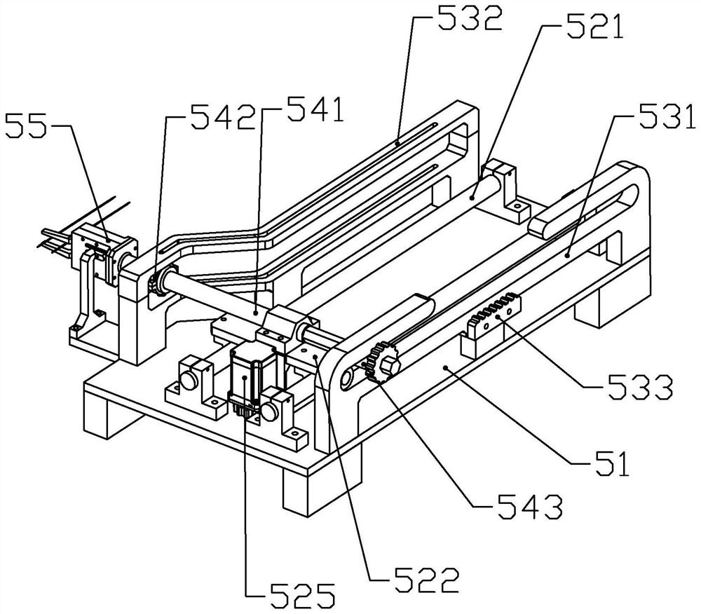
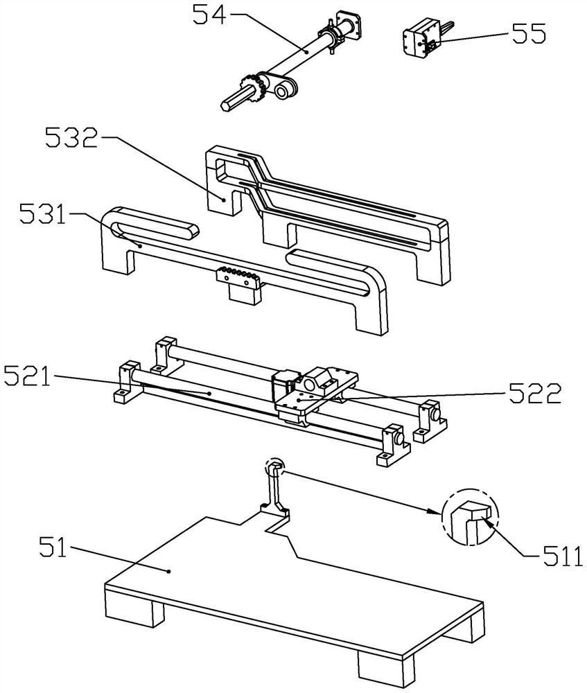
[0042] according to Figure 1 to Figure 8 As shown, the wire moving and turning mechanism of a solar panel wire bonding machine described in this embodiment includes a mounting base 51, a sliding plate 522 slidably connected to the mounting base 51, and a sliding plate 522 fixedly connected to the sliding plate 522. The wire-moving motor 525 for driving the slide plate 522 to slide; the slide plate 522 is rotatably connected with an overturning portion 54; the direction of the rotation axis of the overturning portion 54 is perpendicular to the sliding direction of the slide plate 522; One end of the turning part 54 is fixedly connected with a clamping part 55 for clamping the wire; the turning part 54 includes a turning bar 541 rotatably connected to the sliding plate 522, which is slidably connected along the axial direction of the turning bar 451. The flip sliding tube 543 on the outer periphery of the flip rod 541 for driving the flip rod 541 to rotate in the circumferentia...

Embodiment 2

[0076] according to Figure 1 to Figure 17 As shown, a solar panel automatic cutting and welding machine described in this embodiment includes a workbench, a positioning assembly 1 installed on the workbench for placing solar panels, and a positioning assembly 1 installed on the workbench The feeding assembly 2 used to place the solar panel to the positioning assembly 1, the tangent assembly 3 installed on the workbench for wire cutting and tinning, the tangent assembly 3 installed on the workbench for holding liquid tin Tin dipping assembly 4, a wire moving assembly 5 installed on the workbench for moving and flipping wires, a pull wire assembly 6 installed on the workbench for straightening wires, and a wire assembly installed on the workbench The wire branch assembly 7 for moving the separated wires, the welding assembly 8 installed on the workbench for welding the wires to the solar panel, and the solar panel installed on the workbench for moving the welded wires Take the...


PUM


Abstract

The invention discloses a wire moving and overturning mechanism of a solar panel wire welding machine. The wire moving and overturning mechanism comprises a mounting base, a sliding plate and a wire moving motor, the sliding plate is rotationally connected with an overturning part; one end of the overturning part is fixedly connected with a clamping part; the overturning part comprises an overturning rod, an overturning sliding pipe and a guide ring; the mounting base is fixedly connected with an overturning rack and a telescopic track; the telescopic track is composed of two straight track sections and an inclined track section. When the guide ring slides in the straight rail, the turnover rod rotates in the circumferential direction; and when the guide ring slides in the inclined rail, the overturning rod axially slides. According to the invention, a wire can be clamped, the clamping action is rapid, and the sheath of the wire cannot be flattened or damaged; the wire can be moved and overturned, so that the clamping end of the wire faces and moves to the next station, the control difficulty is reduced, and the failure rate is reduced; automatic operation is adopted, using is easy and convenient, manual intervention is not needed, and economic benefits are improved.

Description

technical field [0001] The invention belongs to the technical field of automation equipment, and in particular relates to a wire moving and turning mechanism of a solar panel wire bonding machine. Background technique [0002] The Chinese patent document whose document number is CN112397612A discloses a kind of automatic wire cutting and welding equipment for solar panels. Mechanism, wire drawing module, welding module, small tin furnace module, wire taking mechanism, feeding mechanism, discharging mechanism, dividing plate and branching mechanism, tin wire and wire conveying mechanism, the tin dipping and shearing mechanism and welding mold The assembly is an important part. The device adopts a new type of cylinder rotating wire dividing mechanism. At the same time, a slag scraper is installed on the small tin furnace, which can save the amount of tin wire. The rotating tin dipping plate is used to make the wire contact Solder, so that the solder is applied more evenly, an...

Claims


Application Information

Patent Timeline
IPC IPC(8): H01L31/18B23K1/00B23K3/08
CPCH01L31/188B23K1/0008B23K1/0016B23K3/08Y02P70/50
Inventor 吴辉辉
Owner 吴辉辉
Why Eureka
Try Eureka