Efficient heat dissipation double-flow-channel water pump

A double-channel, water-pump technology, which is applied to parts, pumps, and pump components of pumping devices for elastic fluids, can solve problems such as poor cooling efficiency of motors, achieve high cooling efficiency, improve cooling efficiency, and facilitate real-time maintenance Effect

Active Publication Date: 2022-03-25
LEO GRP ZHEJIANG PUMP CO LTD
View PDF5 Cites 3 Cited by
  • Summary
  • Abstract
  • Description
  • Claims
  • Application Information

AI Technical Summary

Problems solved by technology

Its disadvantages are: the flow channel is set on the pump body and the end cover, which can only complete the cooling of the front end of the motor, and the overall cooling efficiency of the motor is poor.

Method used


Image

  • Efficient heat dissipation double-flow-channel water pump
  • Efficient heat dissipation double-flow-channel water pump
  • Efficient heat dissipation double-flow-channel water pump

Examples


Embodiment 1

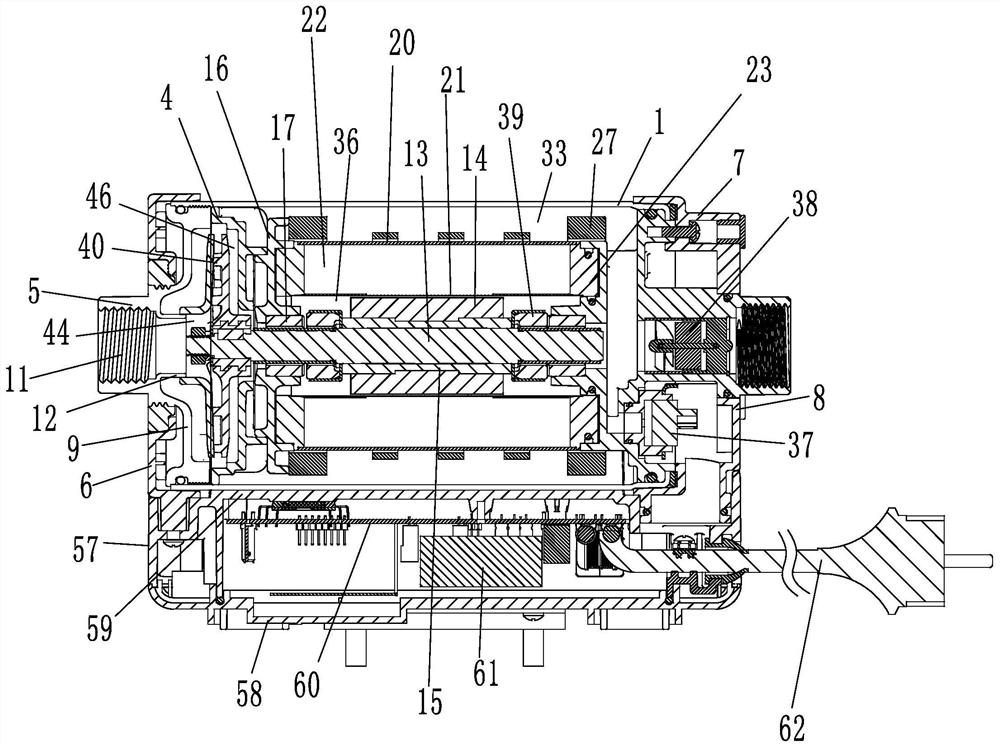
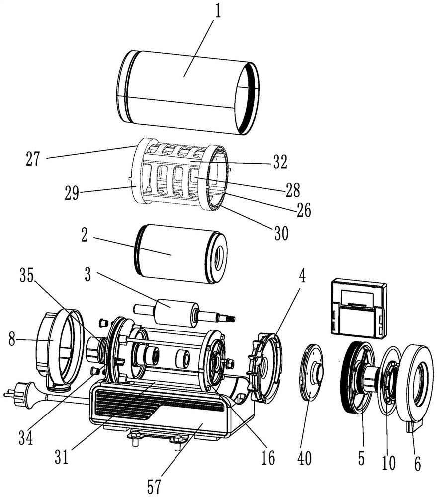
[0055] Such as Figure 1 to Figure 7 As shown, a high-efficiency heat-dissipating double-channel water pump is characterized in that it includes a water pump outer cylinder 1 , a stator assembly 2 , a rotor assembly 3 and a guide casing 4 .

[0056] The shape of the water pump outer cylinder 1 is a cylindrical shape with both ends unobstructed. The water pump also includes a front end cover 5, a front casing 6, a rear end cover 7 and a rear casing 8; along the axial direction of the water pump outer cylinder 1, the front end cover 5. The front housing 6 is respectively fixed on the inner and outer walls of one end of the water pump outer cylinder 1, and the rear end cover 7 and the rear housing 8 are respectively fixed on the inner and outer walls of the other end of the pump outer cylinder. The front end cover 5, the front casing 6, the rear end cover 7 and the rear casing 8 are all circular ring-disk structures. The front end cover 5 includes a front plate body 9 and a fron...

Embodiment 2

[0069] A high-efficiency heat dissipation dual-channel water pump, such as Figure 8 and Figure 9 As shown, the difference between Embodiment 2 and Embodiment 1 is that the shape of the water passage 19 is linear, the cross-sectional shape of the water passage 19 is semicircular, and the axis of the water passage 19 is located on the tangent surface of the inner peripheral side of the bearing 17. Above, the axis of the water passage and the axis of the bearing are arranged obliquely, and the intersection point of the axis of the water passage and the inner peripheral side of the bearing is located in the middle of the bearing axial direction. The water diversion groove 18 is located in the radial direction of the end face of the bearing 17 , chamfers are respectively provided at both ends of the bearing 17 , and the water diversion groove 18 is arranged along the end face of the bearing 17 and the chamfer in a broken line shape.

[0070] When in use, the stator assembly 2 is...


PUM


Abstract

The invention discloses a double-flow-channel water pump with an efficient heat dissipation function. The double-flow-channel water pump comprises a water pump outer cylinder, a stator assembly, a rotor assembly and a flow guide shell. The stator assembly is arranged in the water pump outer cylinder in a sealed mode, the rotor assembly is rotationally arranged in the stator assembly, the water pump outer cylinder and the outer wall of the stator assembly define a first space, and the outer wall of the rotor assembly and the inner wall of the stator assembly define a second space; an impeller connected with the rotor assembly is arranged in the flow guide shell, a mounting cavity matched with the impeller is formed in the flow guide shell, a plurality of vortex grooves are formed in the peripheral wall of the mounting cavity, and a water permeable hole matched with the rotor assembly is formed in the flow guide shell; the water inlet end of the water pump, the vortex groove, the first space and the water outlet end of the water pump form a first flow channel; the water inlet end of the water pump, the permeable hole, the second space and the water outlet end of the water pump form a second runner; a stator support is arranged on the outer side of the stator assembly, and a plurality of cooling grooves are formed in the stator support. The two ends of the stator support are respectively provided with a flow blocking ring.

Description

technical field [0001] The present application relates to the technical field of canned pumps, in particular to a dual-channel water pump with high heat dissipation. Background technique [0002] The pump body and the motor of the canned pump are connected together, and the rotor of the motor and the impeller of the pump body are fixed on the same shaft. Although there is a cooling channel in the prior art to cool down the motor of the canned pump, the cooling channel is set outside the motor, and the cooling effect is not good, and the cooling liquid of the canned pump is set separately from the fluid to be pumped, which is not conducive to the integration of the water pump , increasing the pump cost. [0003] For example, in the Chinese patent literature, the utility model patent No. CN2016214699800 was authorized and announced on August 8, 2017. The application discloses a water pump with an inner flow channel, including a pump body and a motor. The left end of the motor...

Claims


Application Information

Patent Timeline
Patent Type & Authority Applications(China)
IPC IPC(8): F04D13/06F04D29/58F04D29/44H02K5/20H02K7/14H02K9/193
CPCF04D13/06F04D29/586F04D29/5806F04D29/445H02K9/193H02K5/20H02K7/14
Inventor 林荣颜成刚
Owner LEO GRP ZHEJIANG PUMP CO LTD
Why Eureka
Try Eureka