
Laser cutting equipment for metal plate production and processing

A laser cutting and metal plate technology, which is applied in metal processing equipment, laser welding equipment, welding equipment, etc., can solve the problems of metal plate falling on the workbench, low work efficiency, accidental injury of laser cutting head, etc.

Inactive Publication Date: 2022-03-25
江苏昕乔智能科技有限公司
View PDF9 Cites 3 Cited by
  • Summary
  • Abstract
  • Description
  • Claims
  • Application Information

AI Technical Summary

Problems solved by technology

[0003] However, when laser cutting a metal plate, the metal plate needs to be placed at the bottom of the laser cutting head. The metal plate is usually placed on the cutting table, and the cutting is affected by the laser cutting head. The displacement of the metal plate is likely to cause errors in the cutting position. This is not conducive to improving the cutting efficiency; in addition, the metal plate after cutting generally falls on the workbench, and the operator needs to remove it manually, the work efficiency is low, and it is easy to be accidentally injured by the laser cutting head, which is not conducive to improving the use effect of the equipment

Method used


Image

  • Laser cutting equipment for metal plate production and processing
  • Laser cutting equipment for metal plate production and processing
  • Laser cutting equipment for metal plate production and processing

Examples


Embodiment Construction

[0027] In order to make the technical means, creative features, goals and effects achieved by the present invention easy to understand, the present invention will be further described below in conjunction with specific embodiments.

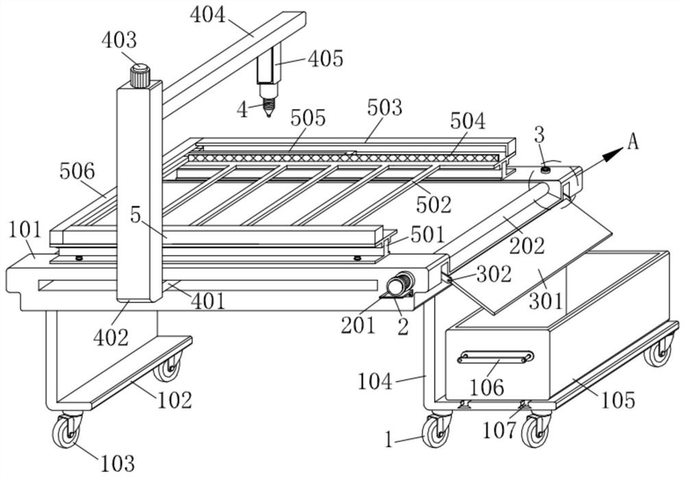
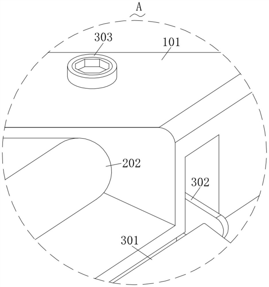
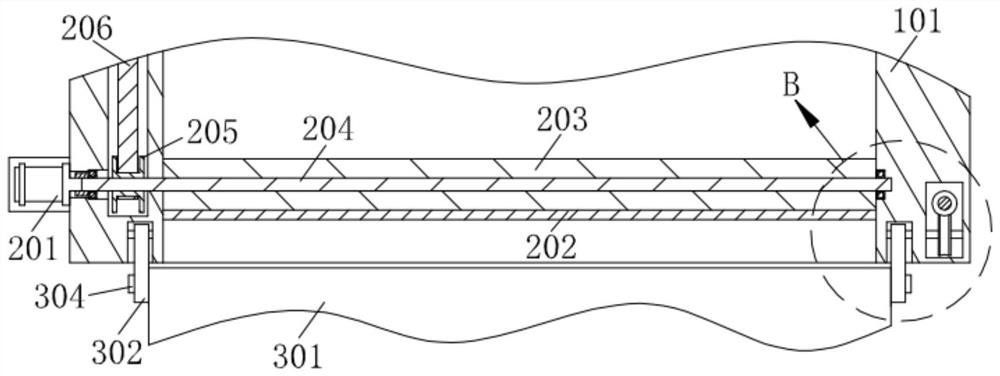
[0028] Such as Figure 1-Figure 9 As shown, a kind of laser cutting equipment for metal plate production and processing according to the present invention includes a main body mechanism 1, and an adjustment mechanism 4 is installed on the main body mechanism 1; a fixing mechanism 5 is connected to the main body mechanism 1; The fixing mechanism 5 is engaged with the limit mechanism 6; the main body mechanism 1 is equipped with a conveying mechanism 2; the main body mechanism 1 is connected with a guide mechanism 3;

[0029]The fixing mechanism 5 includes a mounting plate 506 on which a turning handle 510 is matched and rotated, and the limit mechanism 6 includes a clamping rod 602 on which the mounting plate 506 is engaged and connected with a cla...


PUM


Abstract

The invention relates to the technical field of laser cutting machines, in particular to laser cutting equipment for metal plate production and machining, which comprises a main body mechanism, and an adjusting mechanism is mounted on the main body mechanism in a matched manner; the main body mechanism is connected with a fixing mechanism; a limiting mechanism is clamped on the fixing mechanism in a matched manner; a conveying mechanism is mounted on the main body mechanism; the main body mechanism is connected with a guide mechanism; the metal plate is placed on the fixing mechanism, the limiting mechanism is pulled so that the metal plate can slide out of the fixing mechanism, the fixing mechanism is rotated, then the metal plate can be conveniently clamped and fixed, and therefore the situation that the cutting effect is poor due to the fact that the metal plate is prone to shaking when being cut is advantageously prevented; the cutting piece falls onto the conveying mechanism so that the cutting piece can be conveniently conveyed, the angle of the cutting piece can be conveniently adjusted by rotating the guide mechanism, then the cutting piece can be conveniently stored through the main body mechanism when the cutting piece is conveyed to the guide mechanism, and the labor intensity generated by manually taking the cutting piece can be easily reduced.

Description

technical field [0001] The invention relates to the technical field of laser cutting machines, in particular to a laser cutting device for metal plate production and processing. Background technique [0002] Laser cutting process replaces the traditional mechanical knife with an invisible beam. It has the characteristics of high precision, fast cutting, not limited to cutting patterns, automatic typesetting saves materials, smooth incision, and low processing cost. It will gradually improve or replace it. Traditional metal cutting process equipment. When cutting metal sheets, laser cutting machines are generally used. [0003] However, when laser cutting a metal plate, the metal plate needs to be placed at the bottom of the laser cutting head. The metal plate is usually placed on the cutting table, and the cutting is affected by the laser cutting head. The displacement of the metal plate is likely to cause errors in the cutting position. This is not conducive to improving ...

Claims


Application Information

Patent Timeline
Patent Type & Authority Applications(China)
IPC IPC(8): B23K26/38B23K26/08B23K26/70
CPCB23K26/38B23K26/0869B23K26/083B23K26/702
Inventor 沙欢欢王明珍魏海红
Owner 江苏昕乔智能科技有限公司
Learn More