Intelligent printing and dyeing wastewater treatment device

A treatment device, printing and dyeing wastewater technology, applied in the field of printing and dyeing, can solve the problems that the fiber cannot be cleaned, and it is difficult to remove the fiber in the wastewater, so as to achieve the effect of improving efficiency and intelligence, and speeding up the flow screening speed

Pending Publication Date: 2022-03-25
郭宁
View PDF7 Cites 0 Cited by
  • Summary
  • Abstract
  • Description
  • Claims
  • Application Information

AI Technical Summary

Problems solved by technology

[0005] Aiming at the deficiencies of the prior art, the present invention provides an intelligent printing and dyeing wastewater treatment device, which solves the problem that the existing printing and dyeing wastewater treatment device is difficult to remove the fibrous matter contained in the wastewater, improves the efficiency of wastewater treatment, and can sieve The separated fiber is cleaned and collected, avoiding the problem that the fiber is attached to the inner wall of the waste water tank and cannot be cleaned

Method used


Image

  • Intelligent printing and dyeing wastewater treatment device
  • Intelligent printing and dyeing wastewater treatment device
  • Intelligent printing and dyeing wastewater treatment device

Examples


Embodiment 1

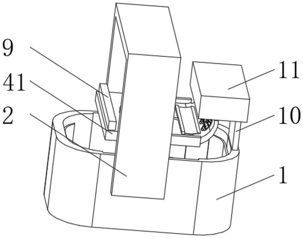
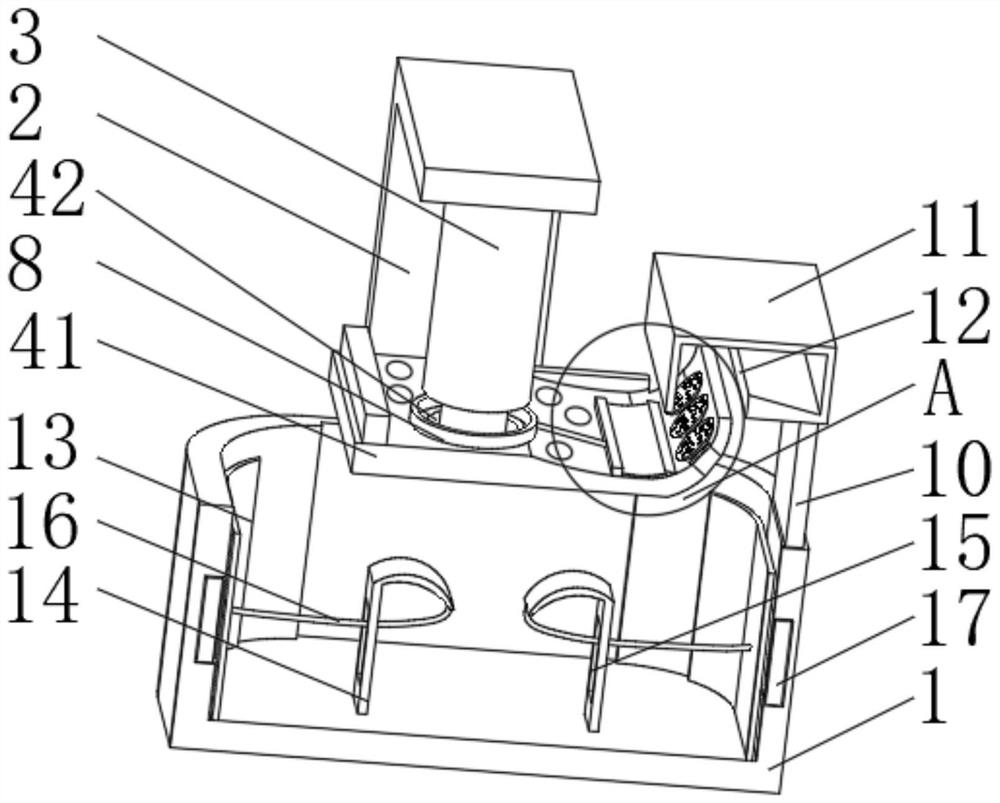
[0034] see Figure 1-4 , the present invention provides a technical solution: an intelligent printing and dyeing wastewater treatment device, including a waste water pool 1, a bracket 2 is fixedly connected to the outside of the waste water pool 1, a hydraulic cylinder 3 is fixedly connected to the inner bottom of the Susohu bracket 2, and the hydraulic cylinder The bottom set of 3 has:

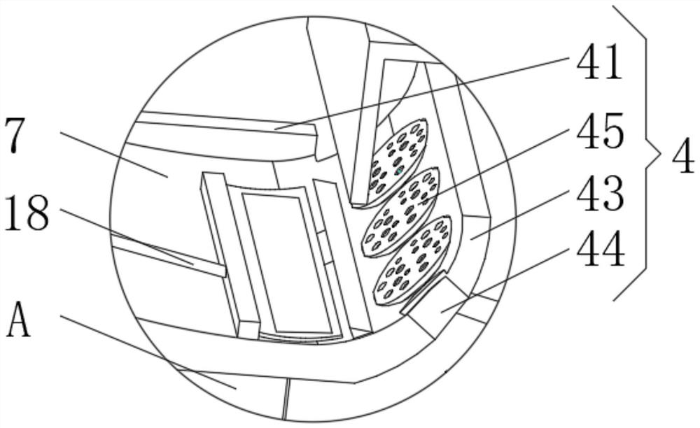
[0035]Screening device 4, the screening device 4 has a screening plate 41, both sides of the inner wall of the waste water tank 1 are provided with longitudinal chute, the screening plate 41 extends to the inside of the longitudinal chute and is slidably connected with the inner wall of the longitudinal chute The top of the screening plate 41 is provided with a mounting hole 42, and one end of the hydraulic cylinder 3 extends to the inside of the mounting hole 42 and is rotatably connected with the screening plate 41. One side of the screening plate 41 is connected with an arc-shaped seesaw 4...

Embodiment 2

[0043] see Figure 1-5 , the present invention provides a technical solution: on the basis of Embodiment 1, a booster device 6 is provided at the bottom of the hydraulic cylinder 3, the booster device 6 has a water storage tank 61, and the water storage tank 61 is evenly opened on the screen plate 41 The top, the inner bottom of the water storage tank 61 is fixedly connected with an elastic plate 62 , and the top of the elastic plate 62 is fixedly connected with a water storage plate 63 .

[0044] The inner bottom of the waste water pool 1 is slidably connected with a water pushing plate 13, and the inner bottom of the waste water pool 1 is fixedly connected with an arc-shaped spring plate 14. One side of the arc-shaped spring plate 14 is provided with a guide hole 15, and the top of the arc-shaped spring plate 14 One end is fixedly connected with a traction rope 16 , and the end of the traction rope 16 away from the arc spring plate 14 passes through the guide hole 15 and is ...


PUM


Abstract

The invention discloses an intelligent printing and dyeing wastewater treatment device which comprises a wastewater pool, the outer side of the wastewater pool is fixedly connected with a support, the bottom of the inner side of the support is fixedly connected with a hydraulic oil cylinder, the bottom of the hydraulic oil cylinder is provided with a screening device, the screening device is provided with a screening plate, and the top of the screening plate is provided with a mounting hole; one end of the hydraulic oil cylinder extends into the mounting hole and is rotationally connected with the screening plate; the cleaning device is provided with a stress plate, and one side of the stress plate is fixedly connected with a push plate; and the boosting device is provided with water storage grooves, and the water storage grooves are evenly formed in the top of the screening plate. According to the intelligent printing and dyeing wastewater treatment device, the purpose of removing fibrous materials contained in wastewater is achieved, the wastewater treatment efficiency is improved, the screened fibrous materials can be cleaned and collected, and the problem that the fibrous materials are attached to the inner wall of a wastewater pool and cannot be cleaned is solved.

Description

technical field [0001] The invention relates to the technical field of printing and dyeing, in particular to an intelligent printing and dyeing wastewater treatment device. Background technique [0002] With the development of textile printing and dyeing industry, the impact of printing and dyeing wastewater on the environment is increasing. Printing and dyeing wastewater refers to the wastewater discharged from the process of pretreatment, dyeing, printing and finishing of cotton, wool, hemp, silk, chemical fiber or blended products. At the same time, textile printing and dyeing wastewater has the characteristics of large water volume, high content of organic pollutants, high alkalinity, and large changes in water quality. Waste of water resources. [0003] The existing printing and dyeing wastewater treatment device is difficult to remove the fiber contained in the wastewater, the efficiency of wastewater treatment is low, the fiber in the screening place cannot be cleane...

Claims


Application Information

Patent Timeline
IPC IPC(8): B01D36/02B01D35/16
CPCB01D36/02B01D35/16
Inventor 郭宁
Owner 郭宁
Why Eureka
Try Eureka