Method for reducing residual vibration of ultrasonic sensor, ultrasonic chip and ultrasonic device

An ultrasonic and sensor technology, applied in the field of ultrasonic chips and ultrasonic devices, can solve the problems of unpredictable, inability to fully compensate the sensor, blind compensation, etc., and achieve the effect of saving compensation time, flexible methods and flexible use.

Pending Publication Date: 2022-03-22
COLIGEN CHINA
View PDF0 Cites 0 Cited by
  • Summary
  • Abstract
  • Description
  • Claims
  • Application Information

AI Technical Summary

Problems solved by technology

[0007] 1. The residual amplitude value of each sensor is different due to discrete reasons, but the compensation pulse amplitude is fixed, so it is impossible to take into account the situation of all sensors, that is, it is impossible to fully compensate all sensors, and the compensation effect is slightly different for each sensor , large discreteness;
[0008] 2. After vibration, the front pulse amplitude is generally large and the rear pulse amplitude is small, but the compensation pulse amplitude is fixed, so the compensation amplitude of the front pulse may not be enough, and the compensation amplitude of the rear pulse is too high, and it is impossible to make good compensation for both front and rear pulses;
[0009] 3. The condition of the previous pulse after aftershock often affects the change of the following pulse. With fixed pulse compensation, it is impossible to predict how the next pulse will change after the previous pulse is compensated. However, the same compensation pulse is still used to compensate, which is a bit blind. ;
[0010] 4. Since the amplitude of the aftershock stage is generally relatively small, and the amplitude of the compensation pulse is fixed throughout, generally only the first few pulses are compensated, and the latter aftershock pulses with small amplitudes are generally not compensated, but these pulses are still after all. part of the vibration, so that the residual vibration cannot be fully compensated, that is, some residual vibration pulses are not compensated, that is, the residual vibration will only have a quantitative change, and cannot produce a sudden reduction change;
[0011] 5. From the above points 1 to 4, it can be seen that there are cases where the compensation is too much or the compensation in the front section is good but the compensation in the back section is not in place, see figure 2 As shown, such a consequence may be sharpening, that is, the overcompensated compensation pulse or the undercompensated after-vibration is mistakenly identified as an obstacle signal and falsely reported. The effect is counterproductive. In reality, many people lack experience in this area. people have suffered from this
[0012] In summary, this aftershock compensation method will only improve, but cannot produce significant reduction changes

Method used


Image

  • Method for reducing residual vibration of ultrasonic sensor, ultrasonic chip and ultrasonic device
  • Method for reducing residual vibration of ultrasonic sensor, ultrasonic chip and ultrasonic device
  • Method for reducing residual vibration of ultrasonic sensor, ultrasonic chip and ultrasonic device

Examples


Embodiment 1

[0049] see Figure 3-Figure 4 As shown, a method for reducing the residual vibration of an ultrasonic sensor in this embodiment includes the following steps:

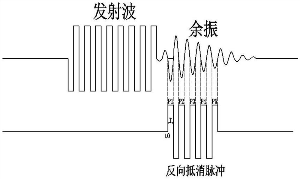
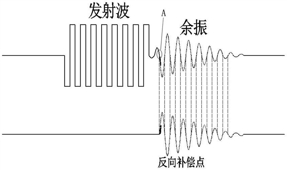
[0050] S1. Use the AD module to sample the amplitude of the first n sampling points of the aftershock of the ultrasonic sensor, where n is a natural number; then use the DA module to output a voltage value with the same amplitude but opposite phase to offset and compensate the first n sampling points; as a specific implementation, see Figure 3-Figure 4 As shown, use AD to sample the amplitude of the first n sampling points of aftershock (such as Figure 4 V1, V2, V3, V4, V5, V6, V7, V8), and then use DA to output voltage values ​​with the same amplitude but opposite phase (ie -V1, -V2, -V3, -V4, -V5, -V6 , -V7, -V8) to offset and compensate the n sampling points;

[0051]S2. Use the AD module to sample the amplitude of the second n sampling points of the aftershock of the ultrasonic sensor, and then use the DA modul...

Embodiment 2

[0059] Corresponding to the method for reducing the residual vibration of the ultrasonic sensor in Embodiment 1, a corresponding ultrasonic chip for reducing the residual vibration of the ultrasonic sensor can be provided, and an AD module and a DA module are integrated in the ultrasonic chip.

[0060] Among them, the AD module is used to sample the amplitude of m times n sampling points of aftervibration of the ultrasonic sensor, wherein n is a natural number, and m is a natural number greater than 2.

[0061] The DA module is used to output voltage values ​​with the same amplitude but opposite phases to offset and compensate n sampling points each time.

[0062] Use the AD module to sample the AD value of each point of the residual vibration, and then output the DA value of the same value but with the opposite phase at the corresponding position to offset the residual vibration. Every time a point is compensated, the AD value of the next point is scanned, and then the DA valu...

Embodiment 3

[0066] A method for reducing the residual vibration of an ultrasonic sensor in this embodiment includes the following steps:

[0067] After ADC sampling, directly control the DAC output signal with the same but opposite phase to the ultrasonic sensor.

[0068] Compared with Embodiment 1, this embodiment also has the advantages of easy implementation, obvious effects, flexible use, and low cost.


PUM


Abstract

The invention discloses a method for reducing residual vibration of an ultrasonic sensor, an ultrasonic chip and an ultrasonic device.The method for reducing the residual vibration of the ultrasonic sensor can adopt a first scheme or a second scheme, the first scheme comprises the following steps that S1, an AD module is used for sampling amplitudes of n sampling points of the residual vibration of the ultrasonic sensor for the first time, and n is a natural number; then outputting voltage values with the same amplitude but opposite phases by using a DA module to offset and compensate the n sampling points of the first time; s2, sampling amplitudes of n sampling points for the second time by using the AD module, and then outputting voltage values with the same amplitude but opposite phases by using the DA module again to offset and compensate; s3, repeating the steps S1 and S2 until the residual vibration value is within a required range; according to the second scheme, after ADC sampling, the DAC is directly controlled to output signals with the same value but opposite phases to the ultrasonic sensor. According to the invention, the residual vibration can be obviously reduced, and the jump is obviously reduced.

Description

technical field [0001] The invention relates to the technical field of sensing and information processing, in particular to a method for reducing residual vibration of an ultrasonic sensor, an ultrasonic chip and an ultrasonic device. Background technique [0002] Ultrasonic sensors have many applications in various fields. For example, in detecting liquid levels, ultrasonic sensors can detect liquid levels of various liquids, detect transparent objects and materials, control tension and measure distances. In terms of reversing radar, anti-collision systems and Ultrasonic sensors are used in automatic parking assistance systems and ADAS systems. Ultrasonic sensors have a very wide range of applications in reversing radar. [0003] The key component of the ultrasonic sensor is the probe core, that is, the piezoelectric ceramic sheet. The probe core is mechanically bent under the driving of the alternating voltage to drive the air to vibrate, thereby sending out the ultrasoni...

Claims


Application Information

Patent Timeline
IPC IPC(8): G01S15/931G01S7/539
CPCG01S15/931G01S7/539
Inventor 黄诚标廖顽强周江勇何德仁林朝辉付杰林志奇
Owner COLIGEN CHINA
Why Eureka
Try Eureka