Fixing equipment for motor detection

A technology of fixing equipment and fixing plates, which is applied in the direction of motor generator testing, parts of electrical measuring instruments, measuring electricity, etc., can solve problems such as motor damage, achieve the effect of improving stability and reducing mutual collisions

Active Publication Date: 2022-03-22
无锡市世源电机有限公司
View PDF13 Cites 1 Cited by
  • Summary
  • Abstract
  • Description
  • Claims
  • Application Information

AI Technical Summary

Problems solved by technology

[0005] In order to improve the problem that the motor is easily damaged, the application provides a fixing device for motor detection

Method used


Image

  • Fixing equipment for motor detection
  • Fixing equipment for motor detection
  • Fixing equipment for motor detection

Examples


Embodiment Construction

[0034] The following is attached Figure 1-6 The application is described in further detail.

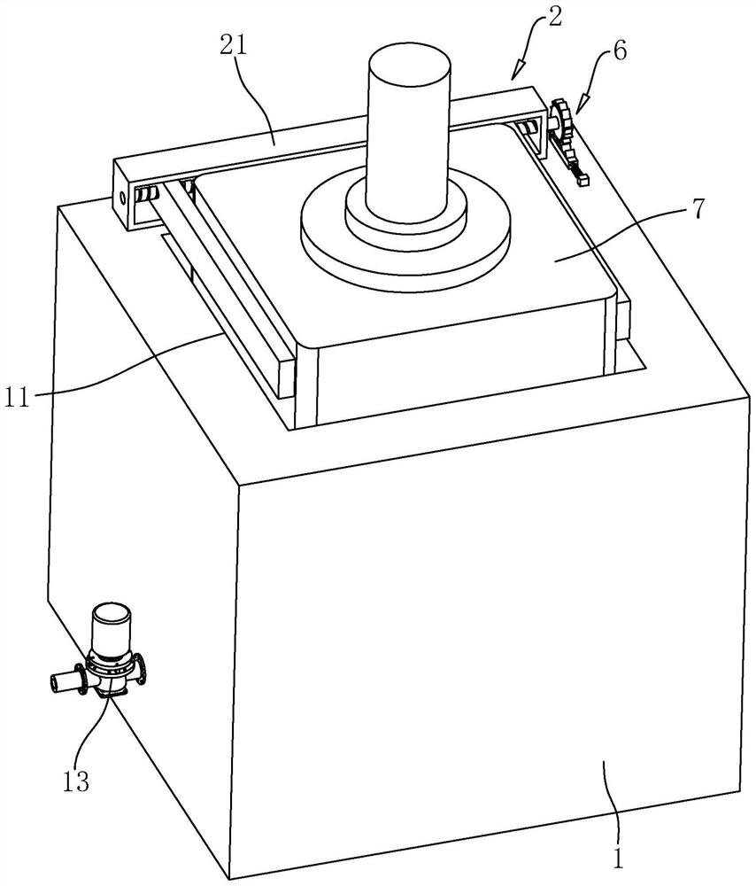
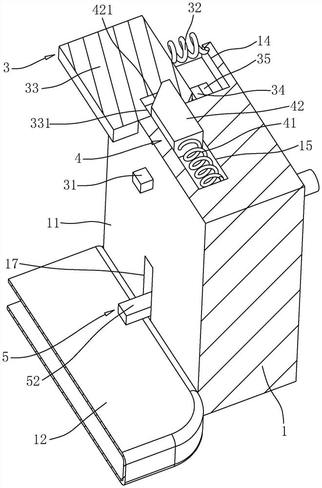
[0035] The embodiment of the present application discloses a fixing device for motor detection. refer to figure 1 and figure 2 , the fixed equipment for motor detection includes a fixed plate 1, the top of the fixed plate 1 is vertically provided with a fixed groove 11, the motor 7 is vertically placed in the fixed groove 11, the output shaft of the motor 7 is arranged vertically upward, and the side wall of the motor 7 There is a gap between the inner wall of the fixed groove 11; the inner bottom surface of the fixed groove 11 is fixedly connected with an inflatable cushion 12, and the inflatable cushion 12 is horizontally placed under the motor 7, and the bottom of the motor 7 is in contact with the top of the inflatable cushion 12. The side wall of pad 12 is in contact with the inner wall of fixed groove 11; The outer wall of fixed plate 1 is fixedly connected with suction pum...


PUM


Abstract

The invention relates to the field of motor testing, in particular to fixing equipment for motor detection, which comprises a fixing plate, a fixing groove for placing a motor is formed in the end face of the fixing plate, and a locking part for locking the motor is mounted on the end face, on the same side as the fixing groove, of the fixing plate. An inflatable cushion arranged below the motor is fixedly connected to the inner bottom face of the fixing groove, and an air draft pump communicating with the inflatable cushion is fixedly connected to the fixing plate. The problem that the motor is easy to damage is solved.

Description

technical field [0001] The present application relates to the field of motor testing, in particular to a fixed device for motor testing. Background technique [0002] At present, the motor is an electromagnetic device that realizes the conversion or transmission of electric energy according to the law of electromagnetic induction. After the production of the motor is completed, it is necessary to detect various parameters during the use of the motor. fixed. [0003] Related technologies can refer to the Chinese utility model patent whose notification number is CN211928120U, which discloses a motor detection tool and a motor detection device, including a base, a detachable pressing plate fixed on the base, and an adjusting member arranged on the pressing plate and the base; the base The top has a lower cavity; the position corresponding to the lower cavity on the pressing plate has an upper cavity, and the lower cavity and the upper cavity can accommodate the motor; the dist...

Claims


Application Information

Patent Timeline
Patent Type & Authority Applications(China)
IPC IPC(8): G01R1/04G01R31/34
CPCG01R1/0408G01R31/343Y02E60/10
Inventor 缪建国
Owner 无锡市世源电机有限公司
Why Eureka
Try Eureka