
Biogas slurry enzymolysis fermentation tank capable of quantitatively adding enzymolysis agent

A fermentation tank and enzymolysis agent technology, applied in the field of fermentation tanks, can solve the problems of inability to add, lack of fermentation tanks, inconvenient adjustment of dosage control, etc., to achieve the effect of improving enzymolysis efficiency, improving fermentation efficiency, and reducing manpower output

Pending Publication Date: 2022-03-22
北京四良科技有限公司
View PDF6 Cites 2 Cited by
  • Summary
  • Abstract
  • Description
  • Claims
  • Application Information

AI Technical Summary

Problems solved by technology

[0003] However, as far as the current traditional biogas slurry enzymatic fermentation tank is concerned, the enzymatic agent is easy to accumulate in a single position after being added, and it requires manpower to spread, which is laborious. It lacks a structure for automatically controlling the discharge of the enzymatic agent. When the enzymatic agent is discharged , the amount control is inconvenient to adjust, quantitative addition is impossible, and the discharge flow of the enzymolysis agent cannot be controlled. The fermentation tank lacks a structure to assist in improving fermentation efficiency, and it is impossible to conveniently add a structure to promote fermentation according to the needs of use.

Method used


Image

  • Biogas slurry enzymolysis fermentation tank capable of quantitatively adding enzymolysis agent
  • Biogas slurry enzymolysis fermentation tank capable of quantitatively adding enzymolysis agent
  • Biogas slurry enzymolysis fermentation tank capable of quantitatively adding enzymolysis agent

Examples


Embodiment

[0030] Example: Please refer to Figure 1 to Figure 8 :

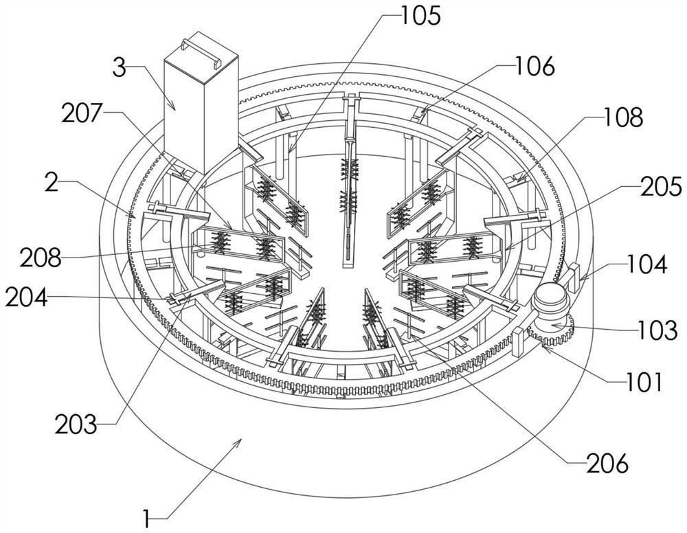
[0031]The present invention proposes a biogas slurry enzymatic fermentation tank capable of quantitatively adding an enzymatic hydrolysis agent, comprising: a main body 1; the main body 1 is the main body of the fermentation tank, and the main body 1 is a disc-shaped structure, so that the biogas slurry can be stored inside the main body 1 Enzymolysis, the inside of the main body 1 is provided with support rods 105, the top of the two support rods 105 is provided with a contact piece 106, and the top of the contact piece 106 is provided with a pull groove 108 inside, the pull groove 108 is a T-shaped structure, and the pull groove 108 The upper part of the inside is an inclined structure, which is used to contact the bottom of the pull piece 304, and then pull the pull piece 304 to move downward, so that the moving rod 303 can also move downward, so that the enzymolysis agent can be discharged through the trough 305; P...


PUM


Abstract

The invention provides a biogas slurry enzymolysis fermentation tank capable of quantitatively adding an enzymolysis agent, and relates to the technical field of fermentation tanks, the biogas slurry enzymolysis fermentation tank is characterized in that a main body is a fermentation tank body, a supporting rod is arranged in the main body, a contact piece is arranged at the top end of the supporting rod, a pull groove is formed in the top end of the contact piece, the pull groove is of a T-shaped structure, and the upper part of the interior of the pull groove is of an inclined structure. During use, a motor controls a rotating part to rotate, a storage part rotates along with the rotating part, the bottom of a pull part can be automatically stressed to be inserted into a pull groove, the inner top end of the pull groove is of an inclined structure, the pull part is pulled downwards, a moving rod moves along with the pull part, a discharging groove can be exposed, and an enzymolysis agent can be discharged downwards; according to the biogas slurry enzymolysis fermentation tank, an enzymolysis agent can be uniformly scattered in the main body, manpower output is reduced, and the problems that the biogas slurry enzymolysis fermentation tank is easy to accumulate at a single position after the enzymolysis agent is added, manpower is needed for scattering, labor is wasted, and a structure for automatically controlling the discharging of the enzymolysis agent is lacked are solved.

Description

technical field [0001] The invention relates to the technical field of fermentation tanks, in particular to a biogas slurry enzymolysis fermentation tank capable of quantitatively adding an enzymatic hydrolysis agent. Background technique [0002] When the biogas slurry is fermented, it usually needs to be fermented in a fermentation tank. During the fermentation process, it is usually necessary to add an enzymatic hydrolysis agent to carry out enzymatic fermentation; [0003] However, as far as the current traditional biogas slurry enzymatic fermentation tank is concerned, the enzymatic agent is easy to accumulate in a single position after being added, and it requires manpower to spread, which is laborious. It lacks a structure for automatically controlling the discharge of the enzymatic agent. When the enzymatic agent is discharged , the dosage control is inconvenient to adjust, the quantitative addition cannot be performed, the discharge flow of the enzymolysis agent can...

Claims


Application Information

Patent Timeline
Patent Type & Authority Applications(China)
IPC IPC(8): C12M1/40C12M1/10C12M1/00C12M1/02C12M1/36
CPCC12M21/18C12M23/00C12M27/10C12M23/48C12M23/52C12M27/02C12M41/44
Inventor 于家伊刘墨任忠秀张长春杨明哲武金辉
Owner 北京四良科技有限公司
Learn More