Carbon dioxide absorber matched with multifunctional connecting mechanism
A connection mechanism, carbon dioxide technology, applied in the direction of respirators, chemical instruments and methods, gas treatment, etc., can solve the problems of medical equipment that cannot be used in time, delay the operation process, and unfavorable surgery for patients, so as to improve the connection adaptability, The effect of improving connection quality and ensuring connection efficiency
- Summary
- Abstract
- Description
- Claims
- Application Information
AI Technical Summary
Problems solved by technology
Method used
Image
Examples
Embodiment 1
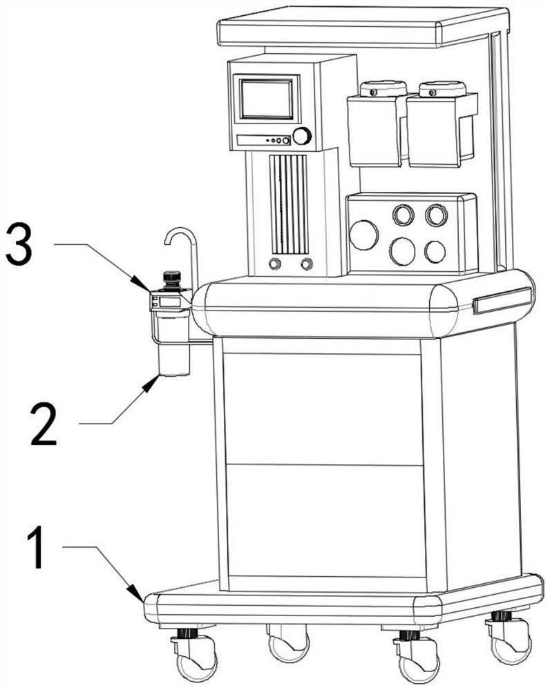
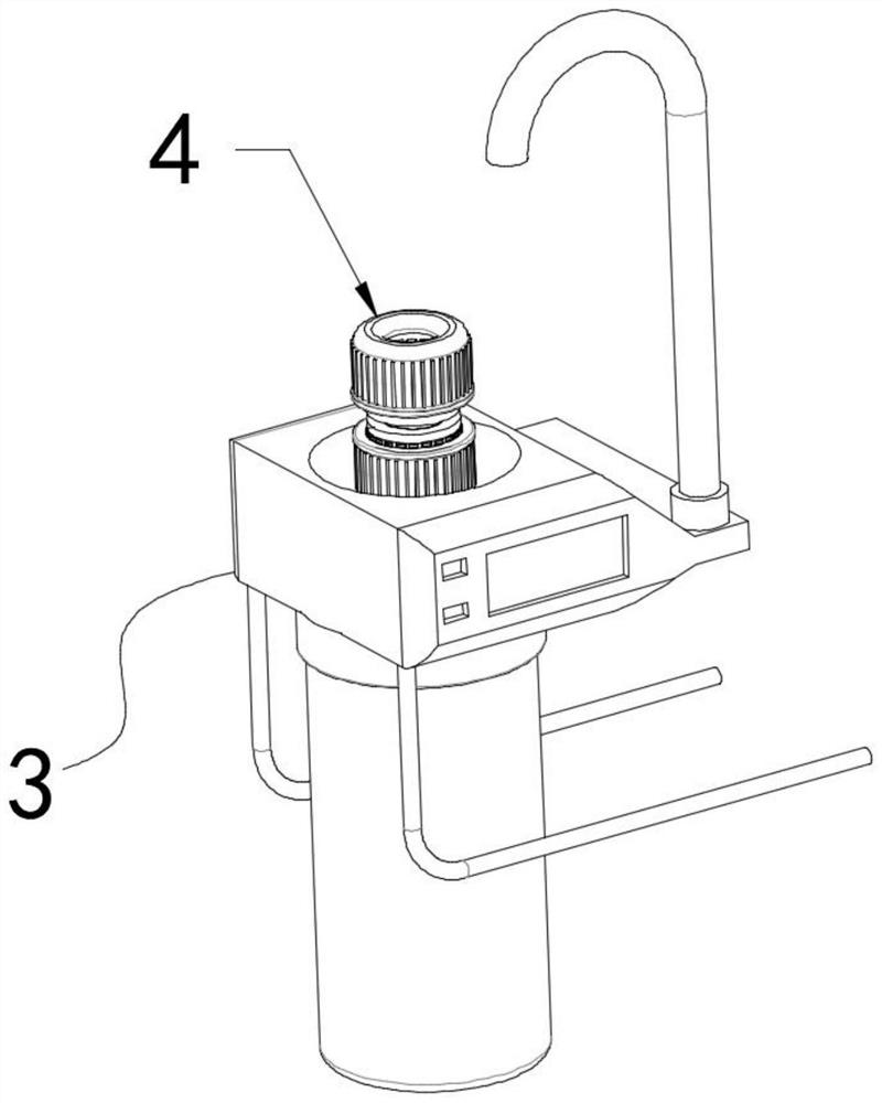
[0030] refer to Figure 1-7, a carbon dioxide absorber adapted with a multifunctional connection mechanism, including a medical device 1, one side of the medical device 1 is connected to an absorber body 2 through a connecting seat 3, and the top of the absorber body 2 is connected to a pipe body 5, and the pipe The body 5 is connected to the connecting base 3 through the docking part 6. The docking part 6 includes a connecting ring 606 and two connecting blocks 602 symmetrically arranged on both sides of the connecting ring 606. The opposite sides of the two connecting blocks 602 pass through the connecting rod 607. The plate frame 603 connected with the connecting ring 606 is rotatably connected to the docking rod 607 and the connecting block 602. There are several limit rods arranged horizontally on the top of each plate frame 603 and on the side close to the connecting block 602. 604, the bottom of the two docking rods 607 and the side away from the connecting block 602 ar...
Embodiment 2
[0033] refer to Figure 1-7 One side of the connection seat 3 is detachably connected to the outer wall of the medical device 1, and both sides of the bottom of the connection seat 3 are provided with a support frame 301 connected to the outer wall of the medical device 1, and the front views of the two support frames 301 are L-shaped, one end of the vertical section of the two support frames 301 is fixedly connected to the bottom of the connecting seat 3, one end of the horizontal section of the two support frames 301 is detachably connected to the outer wall of the medical device 1, and the ring baffle 303 The outer wall of the connecting seat 3 is fixedly connected with the inner wall of the connecting seat 3, and the size of the inner ring of the annular baffle 303 is adapted to the length of the two docking rods 607, and the ends of the two docking rods 607 close to the pipe body 5 are connected to each other through the pin shaft. The two inner sidewalls of the board fra...
Embodiment 3
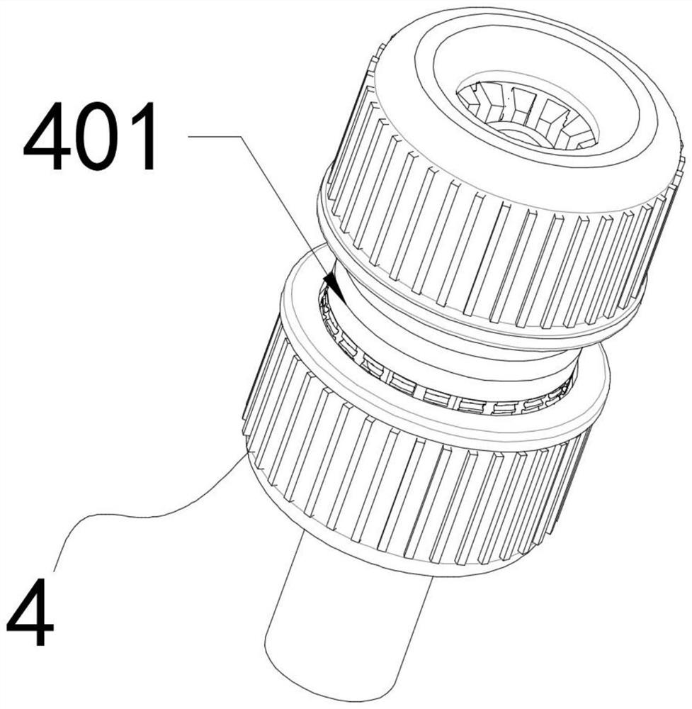
[0035] refer to Figure 1-7 The top of the pipe body 5 is provided with a connecting part 4, the connecting part 4 includes a through pipe 401 and two tapered pipes 403 symmetrically arranged on the top and bottom of the through pipe 401, and the opposite ends of the two tapered pipes 403 are connected to the through pipe. The pipes 401 are connected, and the outer rings of the two tapered pipes 403 are provided with a plurality of conflicting rods 406 fixedly connected with the through pipes 401 along the circumferential direction of the tapered pipes 403. Each conflicting rod 406 is close to one side of the tapered pipe 403 The top position is fixedly connected with the interference claw 405, and the opposite end of the two tapered pipes 403 is provided with a connecting cap 404, and the outer wall of each interference rod 406 is provided with an external thread 402, and the inner ring of each connecting cap 404 is There are internal threads adapted to several conflicting ro...
PUM
 Abstract
Description
Claims
Application Information
 - Generate Ideas
- Intellectual Property
- Life Sciences
- Materials
- Tech Scout
- Unparalleled Data Quality
- Higher Quality Content
- 60% Fewer Hallucinations
Browse by: Latest US Patents, China's latest patents, Technical Efficacy Thesaurus, Application Domain, Technology Topic, Popular Technical Reports.
© 2025 PatSnap. All rights reserved.Legal|Privacy policy|Modern Slavery Act Transparency Statement|Sitemap|About US| Contact US: help@patsnap.com


