
Clamp, clutch test equipment and clutch test method

A technology for testing equipment and clutches, which is applied in the testing of machines/structural components, testing of mechanical components, instruments, etc., and can solve the problems of low disassembly and replacement efficiency, poor compatibility, and high cost

Pending Publication Date: 2022-03-18
GUANGDONG GOBAO ELECTRONICS TECH CO LTD
View PDF0 Cites 0 Cited by
  • Summary
  • Abstract
  • Description
  • Claims
  • Application Information

AI Technical Summary

Problems solved by technology

During the test, the installation before the test and the disassembly after the test are heavy workload; and after the specification of the clutch changes, it is necessary to disassemble the supporting fixture again, and the efficiency of disassembly and replacement is low, and the adaptability is poor, or a new one needs to be made. Test equipment, resulting in high cost and poor compatibility

Method used


Image

  • Clamp, clutch test equipment and clutch test method
  • Clamp, clutch test equipment and clutch test method
  • Clamp, clutch test equipment and clutch test method

Examples


Embodiment 1

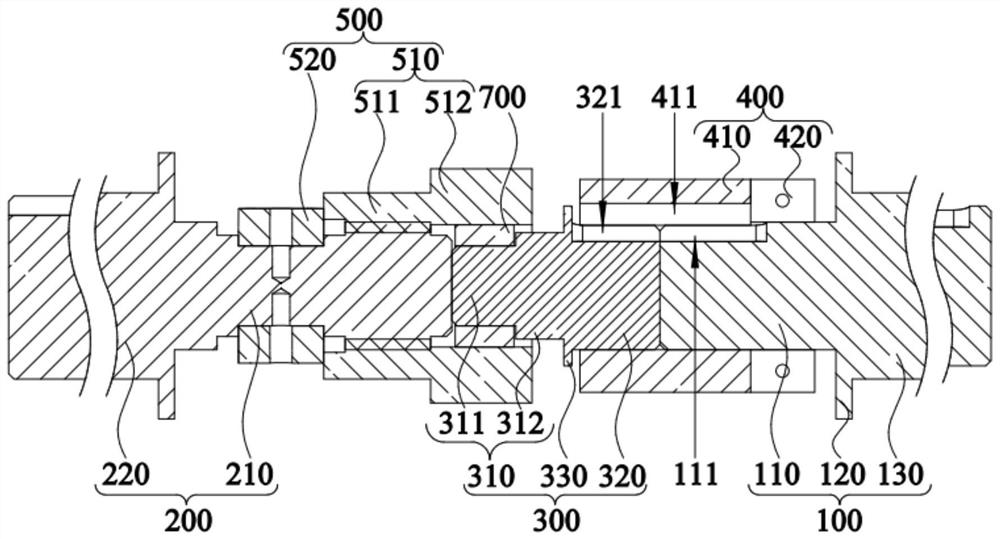
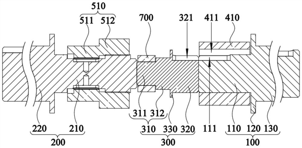
[0067] With the improvement of machining technology, the application of clutch 700 in various instrument and equipment fields is becoming more and more extensive. Clutch 700 is a common component in mechanical transmission, which can separate or engage the transmission system at any time. The basic requirements are: smooth joint, rapid and thorough separation; convenient adjustment and repair; small external size; small mass; good wear resistance and sufficient heat dissipation capacity; Two types of friction. In order to ensure that the clutch 700 is running stably, testing the clutch 700 is an essential step.

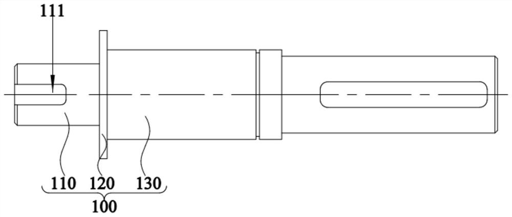
[0068] This embodiment provides a fixture, through which the clutch 700 is fixed, and installed on the driving member, and the driving member is used to drive the fixture loaded with the clutch 700 to rotate at a high speed, and then the durability test of the clutch 700 is carried out so that the clutch 700 meets Use performance.

[0069] like figure 1 and figu...

Embodiment 2

[0096] This embodiment provides a clutch testing method. Through the above fixture, the assembly steps of the clutch 700 before testing are as follows:

[0097] The first fixing assembly 400 is sleeved on the driving shaft 100 and positioned at the second position, and the second fixing assembly 500 is sleeved on the driven shaft 200 and positioned at the fourth position;

[0098] The clutch 700 is sleeved on the installation shaft 300;

[0099] Slide the first fixing component 400 to the first position to connect and fix the installation shaft 300 with the driving shaft 100;

[0100] sliding the second fixing assembly 500 to the third position to connect and fix the mounting shaft 300 with the driven shaft 200; and


PUM


Abstract

The invention relates to the technical field of mechanical testing, in particular to a clamp, clutch testing equipment and a clutch testing method. The clamp comprises a driving shaft, a driven shaft, mounting shafts, a first fixing assembly and a second fixing assembly, the mounting shafts comprise multiple types, each type of mounting shaft corresponds to a to-be-tested clutch in a one-to-one mode, the mounting shafts are detachably arranged between the driving shaft and the driven shaft, the to-be-tested clutch is arranged on the mounting shafts in a sleeving mode, and the first fixing assembly is connected with the second fixing assembly. Therefore, the clamp can be suitable for clutches of different models by replacing the corresponding mounting shafts, and the application range of the clamp is widened. The clamp can be suitable for clutches of different specifications, the compatibility of the clamp is improved, and the working efficiency is improved. The invention further provides clutch testing equipment, the adaptability and compatibility of the clutch testing equipment are improved, and the detection efficiency is improved. The invention further provides a clutch testing method, the mounting shaft is convenient to assemble and disassemble, the remodeling time is shortened, and the remodeling efficiency is improved.

Description

technical field [0001] The invention relates to the technical field of mechanical testing, in particular to a fixture, clutch testing equipment and a method. Background technique [0002] With the improvement of machining technology, the application of clutches in various instrument and equipment fields is becoming more and more extensive. Clutches are common components in mechanical transmissions that can disengage or engage the transmission system at any time. The basic requirements are: smooth joint, rapid and thorough separation; convenient adjustment and repair; small external size; small mass; good wear resistance and sufficient heat dissipation capacity; Two types of friction. In order to ensure the stability of the clutch operation process, the test of the clutch is an essential step. [0003] In the prior art, the clutch durability test is carried out by clutch testing equipment. The clutch testing equipment generally includes a driving part and a jig, wherein t...

Claims


Application Information

Patent Timeline
Patent Type & Authority Applications(China)
IPC IPC(8): G01M13/022B25B11/00
CPCG01M13/022B25B11/00
Inventor 吴在林
Owner GUANGDONG GOBAO ELECTRONICS TECH CO LTD
Learn More