Method for operating can changer, can changer and textile machine

A can replacement and changer technology, applied in the directions of transportation and packaging, transportation of filamentous materials, thin material processing, etc., can solve the problems of consumption structure and inability to use

Active Publication Date: 2022-03-18
TRUETZSCHLER GRP SE
View PDF14 Cites 0 Cited by
  • Summary
  • Abstract
  • Description
  • Claims
  • Application Information

AI Technical Summary

Problems solved by technology

The disadvantages of this concept are the mechanically complex construction and the fact that the concept cannot be applied to textile machines with integrated can filling stations (such as draw frames, sliver coilers, combers), where The coil head is fixed in the textile machine

Method used


Image

  • Method for operating can changer, can changer and textile machine
  • Method for operating can changer, can changer and textile machine
  • Method for operating can changer, can changer and textile machine

Examples


Embodiment Construction

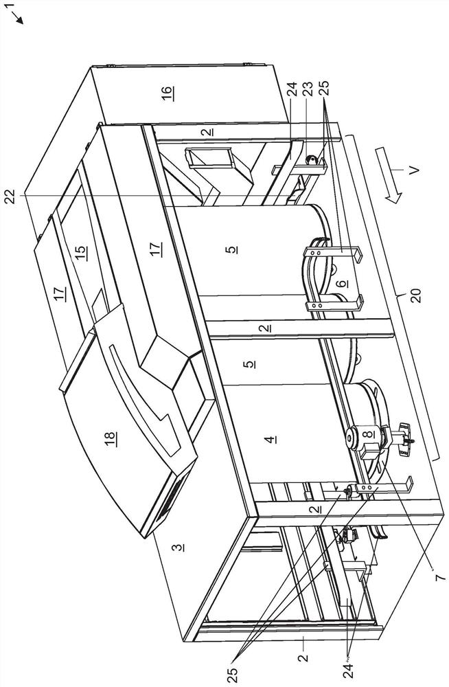
[0034] figure 1 A drawing frame 1 with a can changing section 20 according to one embodiment of the invention is shown. The draw frame 1 is designed here in a non-adjustable manner and includes a drawing section, not shown here, which is designed in a known manner.

[0035] The drafting section comprises a drafting mechanism hood 18 which covers the drafting mechanism and the can storage device located beneath it. Both of these are known and not described further.

[0036] Arranged upstream of the drafting unit in the processing direction V indicated by the square arrow is a feed table 15 via which the fiber sliver is fed from the cans via the creels into the drafting unit in the usual manner. On the side of the drafting mechanism cover 18 there is a side cover 17 which covers other components of the drawing frame 1 , such as drive belts, guide rollers of the drafting mechanism etc.

[0037] Upstream of the feed table 15 in the process direction V, the draw frame 1 preferab...


PUM


Abstract

The invention relates to an operating method for a can changer having a pre-parking position, an intermediate parking position, a can filling position and a drive section, comprising a can changing process having a first sub-process. If only one parking position has a can, the first sub-process is carried out, and the drive device is actuated, so that the can pusher moves and the can is moved into the can filling position. A return movement of the can pusher is then performed. If a can is present in both parking positions, the drive is actuated in a second sub-process such that the can pusher moves the can standing in the pre-parking position into the intermediate parking position and moves the can in the intermediate parking position into the can filling position. And then a return motion is carried out. The can changer has a can filling section and a can changing section, is designed to fill a can standing in a can filling position, and comprises a drive section. A processing section of the textile machine for processing fiber material is coupled to the can changer on the output side.

Description

technical field [0001] The invention relates to a method for operating a can changer, a can changer designed therefor, and a textile machine equipped with the can changer. Background technique [0002] The can changer is used for automatically changing cans filled with fiber material with empty cans in order to fill said empty cans. [0003] There are essentially three concepts for this, in which the can is moved for the can change: [0004] The first concept involves a so-called rotary can changer, in which empty cans are moved by means of guide rails in a circle around the center point of rotation of the turnstile by means of a turnstile with usually three arms, wherein the full cans are moved by means of One arm moves away from the can filling position, the following empty can is moved to the can filling position by means of the second arm and the third arm is rotated in such a way that it can receive the following full can at the next can change The second barrel of th...

Claims


Application Information

Patent Timeline
Patent Type & Authority Applications(China)
IPC IPC(8): B65H67/06
CPCB65H67/063B65H67/067B65H67/068B65H67/061B65H67/0428B65H2701/311
Inventor 马赛尔·施塔霍默
Owner TRUETZSCHLER GRP SE
Why Eureka
Try Eureka