


Quick Research
Generate reliable direction feasibility study reports for your R&D in just a few steps.

Technical Q&A
Discover and master advanced knowledge NOW. Basics, ideas, possibilities, all at once.

Find Solutions
As an expert in R&D theories, this can generate solutions to your technical problems instantly.

Evaluate Feasibility
Analyze your overall solution with one click, know your potential R&D risks in advance.

Monitor Landscape
Get weekly tech updates, stay abreast of the latest tech innovations and key insights.
Novel house building wall structure
A technology for building walls and new houses, applied in building components, building structures, buildings, etc., can solve problems such as reduced performance, waste of building materials, hidden safety hazards, etc., to improve performance, reduce limitations, and stabilize good effect
- Summary
- Abstract
- Description
- Claims
- Application Information
AI Technical Summary
Problems solved by technology
Method used
Image

Examples
Embodiment example 1
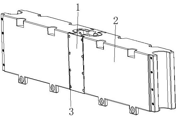
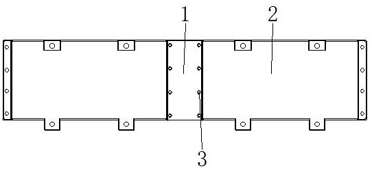
[0032] see Figure 1-6 , the present invention provides a technical solution: a new wall structure for building construction, including a connecting device 1, a wall panel device 2, and fixing bolts 3, and the wall panel device 2 is mated and connected on both sides corresponding to the surface end of the connecting device 1 , the fixing bolt 3 is threadedly connected to the position corresponding to the end of the surface of the connecting device 1 and the surface of the wall panel device 2;
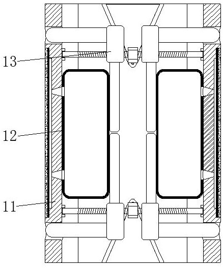
[0033]The connection device 1 is provided with a base device 11, an elastic air bag 12, and a locking device 13. The surface end of the base device 11 is connected with the end of the wall panel device 2, the elastic air bag 12 is arranged on the inner wall of the base device 11, and the locking device 13 is set inside the base device 11 and close to the elastic airbag 12, the entire wall can be quickly spliced into any size, easy to disassemble, save time and effort, strong adaptabil...
Embodiment example 2
[0035] The connection device 1 is provided with a base device 11, an elastic air bag 12, and a locking device 13. The surface end of the base device 11 is connected with the end of the wall panel device 2, the elastic air bag 12 is arranged on the inner wall of the base device 11, and the locking device 13 is arranged inside the base device 11 and close to the position of the elastic airbag 12;
[0036] The base device 11 is provided with a connection base 111, a fan-shaped gap 112, an air cavity 113, an elastic expansion layer 114, and an anti-skid layer 115. inside and located on the surface, the elastic expansion layer 114 is arranged on the surface of the connecting base 111 and at the position of the air cavity 113, and the anti-skid layer 115 is arranged on the surface of the elastic expansion layer 114, when the pressing plate 135 on the locking device 13 is on the connecting block When moving to both sides under the drive of 133, pressure will be applied to the elastic...
Embodiment example 3
[0039] The wall panel device 2 is provided with a wall panel main body 21, a limit pin 22, a pin groove 23, and an internal thread hole 24. The limit pin 22 is arranged at the bottom of the wall panel main body 21 and is located on the surface, and the pin groove 23 is opened on the wall panel main body. 21 , the internal threaded hole 24 is provided inside the wallboard main body 21 and is located at the position of the limit pin 22 and the pin groove 23 .
[0040] The limit pin 22 and the pin groove 23 are located on the same straight line. The limit pin 22 is evenly distributed on the bottom of the wallboard main body 21, and the pin groove 23 is evenly distributed on the surface top of the wallboard main body 21. By using the limit pin 22 and the pin groove 23 Cooperate and fix through the internal threaded hole 24, and then assemble the connecting device 1 and the wall panel device 2, which can be continuously spliced, and then spliced and disassembled quickly and conven...
PUM
 Abstract
Description
Claims
Application Information
 - R&D Engineer
- R&D Manager
- IP Professional
- Industry Leading Data Capabilities
- Powerful AI technology
- Patent DNA Extraction
Browse by: Latest US Patents, China's latest patents, Technical Efficacy Thesaurus, Application Domain, Technology Topic, Popular Technical Reports.
© 2024 PatSnap. All rights reserved.Legal|Privacy policy|Modern Slavery Act Transparency Statement|Sitemap|About US| Contact US: help@patsnap.com