Progressive drawing die and operation method thereof
A deep drawing die and progressive technology, applied in the field of progressive deep drawing dies, can solve problems such as difficult deep drawing forming, and achieve the effects of avoiding cumulative errors, saving manufacturing costs, and shortening the forming cycle
- Summary
- Abstract
- Description
- Claims
- Application Information
AI Technical Summary
Problems solved by technology
Method used
Image

Examples
Embodiment 1
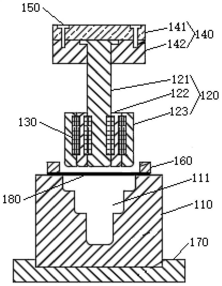
[0040] refer to Figure 1-Figure 7 , the present embodiment provides a progressive drawing die, including a lower mold base 110, a punch assembly 120 and an electromagnet 130, and a molding cavity 111 is opened in the lower mold base 110, and the molding cavity 111 includes multiple layers from The parting cavity is arranged from top to bottom, and the cross-sectional area of the parting cavity decreases successively from top to bottom. The punch assembly 120 includes a central punch 121, and a middle punch 122 is set on the center punch 121. The middle punch 122 is sleeved with an outer layer punch 123, the center punch 121, the middle punch 122 and the outer layer punch 123 can move relative to each other in the vertical direction, the center punch 121, the middle punch 122 and the outer layer punch Die 123 can stretch in the corresponding parting cavity, and the two side walls of central punch 121, the two side walls of middle punch 122 and the inner side wall of outer la...
Embodiment 2
[0056] refer to Figure 1-Figure 7 , the present embodiment provides a method for operating a progressive drawing die, comprising the following steps:
[0057] Place the blank 180 at the corresponding position on the top of the lower mold base 110, and give the blankholder 160 a blankholder force to fix the blank 180;
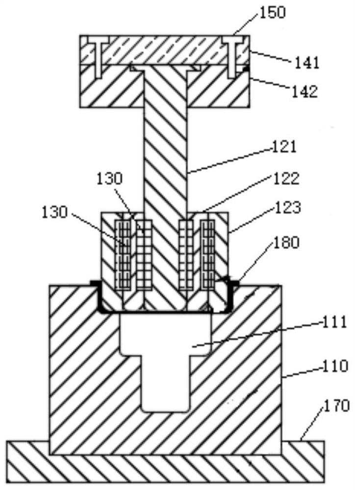
[0058] The punch assembly 120 moves down as a whole until the punch assembly 120 presses the blank 180 into the cavity of the first layer;
[0059] All electromagnets 130 between the middle punch 122 and the outer layer punch 123 are powered off, and the center punch 121 and the middle punch 122 continue to move down to press a part of the blank 180 into the second layer parting cavity. The punch 123 stays in the first layer parting cavity;
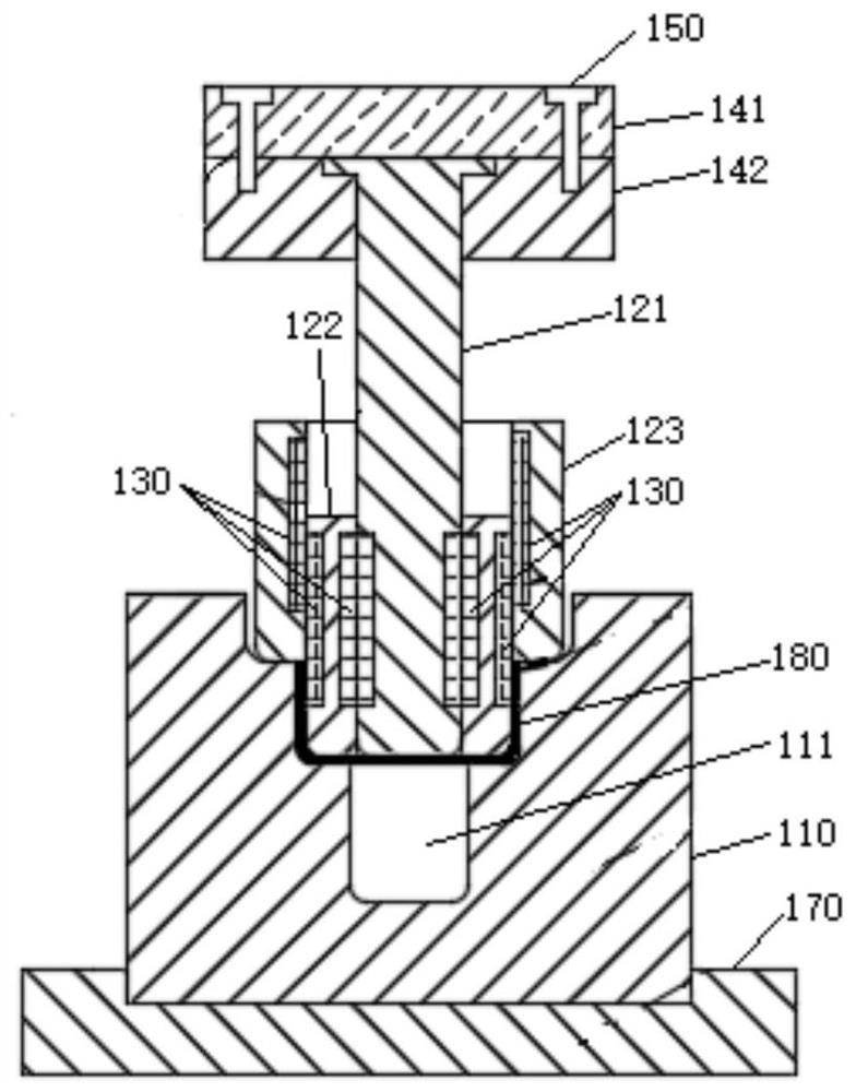
[0060] All the electromagnets 130 between the center punch 121 and the middle punch 122 are powered off, and the center punch 121 continues to move down to press a part of the blank 180 into the third layer parting cavit...
Embodiment 3
[0063] refer to Figure 1-Figure 7 In this embodiment, the intermediate punch 122 in the progressive drawing die is provided with two groups, which are respectively the middle punch A and the middle punch B, the middle punch A is set on the center punch 121, and the middle punch B Set on the middle punch A, the outer layer punch 123 is set on the middle punch B, and the corresponding electromagnet 130 is also embedded between each punch, then the parting cavity should be provided with four layers, so this embodiment A method for operating a progressive drawing die is provided, comprising the following steps:
[0064] Place the blank 180 at the corresponding position on the top of the lower mold base 110, and give the blankholder 160 a blankholder force to fix the blank 180;
[0065] The punch assembly 120 moves down as a whole until the punch assembly 120 presses the blank 180 into the cavity of the first layer;
[0066] All the electromagnets 130 between the middle punch B ...
PUM
 Abstract
Description
Claims
Application Information
 - R&D
- Intellectual Property
- Life Sciences
- Materials
- Tech Scout
- Unparalleled Data Quality
- Higher Quality Content
- 60% Fewer Hallucinations
Browse by: Latest US Patents, China's latest patents, Technical Efficacy Thesaurus, Application Domain, Technology Topic, Popular Technical Reports.
© 2025 PatSnap. All rights reserved.Legal|Privacy policy|Modern Slavery Act Transparency Statement|Sitemap|About US| Contact US: help@patsnap.com