


Quick Research
Generate reliable direction feasibility study reports for your R&D in just a few steps.

Technical Q&A
Discover and master advanced knowledge NOW. Basics, ideas, possibilities, all at once.

Find Solutions
As an expert in R&D theories, this can generate solutions to your technical problems instantly.

Evaluate Feasibility
Analyze your overall solution with one click, know your potential R&D risks in advance.

Monitor Landscape
Get weekly tech updates, stay abreast of the latest tech innovations and key insights.
Multi-cylinder hydraulic correction equipment
A technology for calibrating equipment and hydraulic pressure, applied in metal processing equipment, manufacturing tools, metal processing, etc., can solve the problems of worker safety impact, poor applicability, poor use effect, etc., and achieve the effect of improving accuracy and applicability
- Summary
- Abstract
- Description
- Claims
- Application Information
AI Technical Summary
Problems solved by technology
Method used
Image

Examples
Embodiment 1
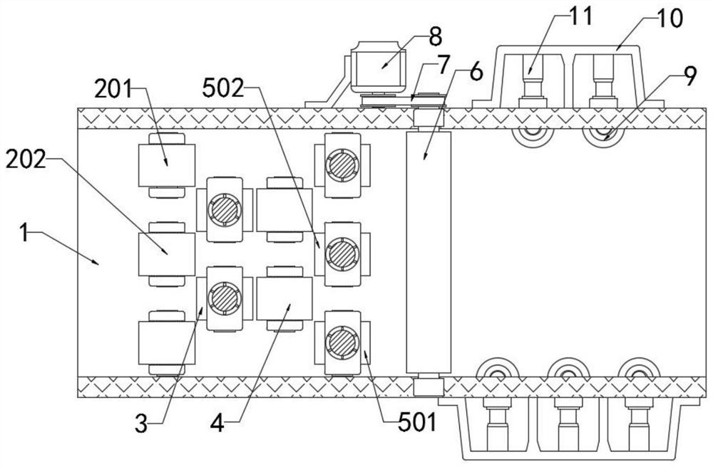
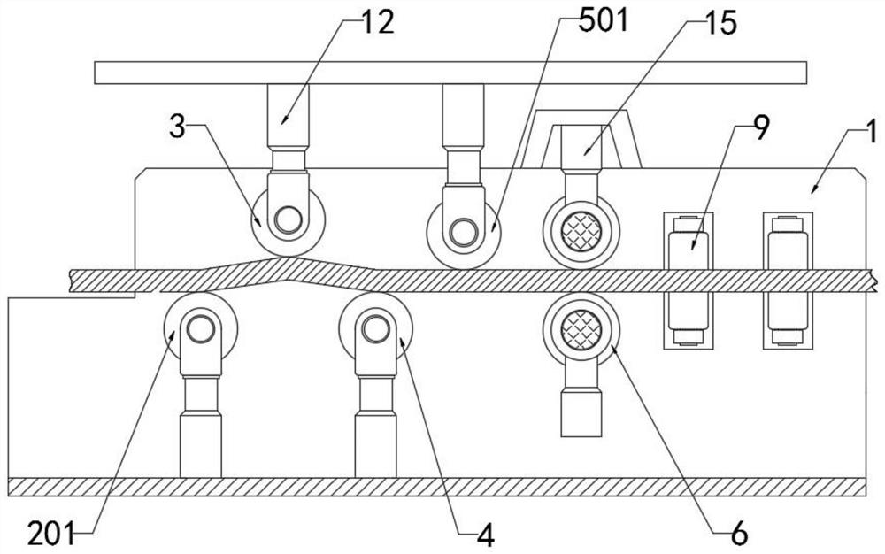
[0022] refer to Figure 1-4 , a multi-cylinder hydraulic correction device, including a correction box 1, two drive rollers 6 are connected to the inner side of the correction box 1 in rotation, and there is a clearance fit between the two drive rollers 6, and two ends of the two drive rollers 6 are provided with The third hydraulic cylinder 15 whose position is transmitted in the vertical direction, and the output end of the third hydraulic cylinder 15 is connected to the drive roller 6 in rotation, and the outer wall of the correction box 1 is fixedly connected with the drive motor 8 by bolts, and the drive motor A transmission chain 7 is arranged between the output shaft of 8 and one of the two drive rollers 6, and the two ends of the transmission chain 7 are respectively sleeved between the drive roller 6 and the output shaft of the drive motor 8, and the inner side of the transmission chain 7 A movable gear plate is provided to adjust the length of the chain so as to ensu...
Embodiment 2
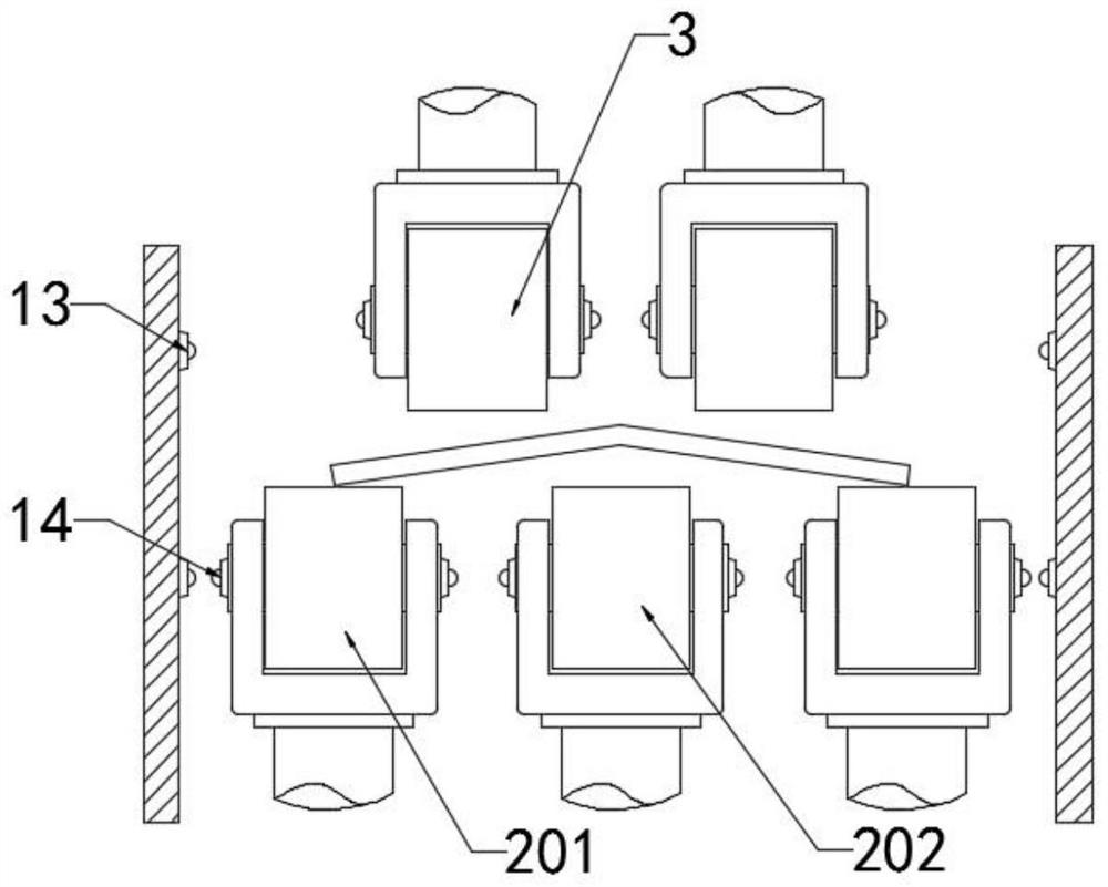
[0024] refer to Figure 1-4 , a multi-cylinder hydraulic correction device, including a correction box 1, two drive rollers 6 are connected to the inner side of the correction box 1 in rotation, and the gap between the two drive rollers 6 is matched, and the upper part of the correction box 1 is sequentially along the horizontal direction of the top view Set the first correction group 2, the second correction group 3, the third correction group 4 and the fourth correction group 5, the bottom of the first correction group 2 and the third correction group 4 and the second correction group 3 and the fourth correction group 5 are provided with the first hydraulic cylinder 12 for its position transmission, the number of rollers in the first correction group 2 and the fourth correction group 5 is the same, the number of rollers in the second correction group 3 and the third correction group 4 is the same, And the first correction group 2, the second correction group 3, and the third...
PUM
 Abstract
Description
Claims
Application Information
 - R&D Engineer
- R&D Manager
- IP Professional
- Industry Leading Data Capabilities
- Powerful AI technology
- Patent DNA Extraction
Browse by: Latest US Patents, China's latest patents, Technical Efficacy Thesaurus, Application Domain, Technology Topic, Popular Technical Reports.
© 2024 PatSnap. All rights reserved.Legal|Privacy policy|Modern Slavery Act Transparency Statement|Sitemap|About US| Contact US: help@patsnap.com