Cable well pipeline breakdown van
A technology for repairing vehicles and cable wells, applied in the field of extinguishing vehicles, can solve the problems of low fire extinguishing efficiency and low safety, achieve the effects of reducing work load, avoiding collisions, and improving fire extinguishing efficiency
- Summary
- Abstract
- Description
- Claims
- Application Information
AI Technical Summary
Problems solved by technology
Method used
Image
Examples
Embodiment 1
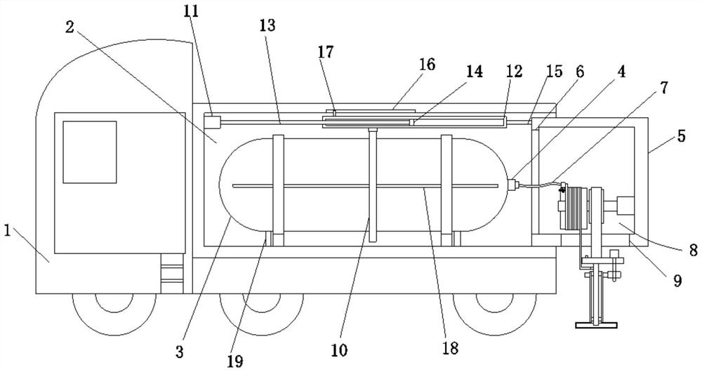
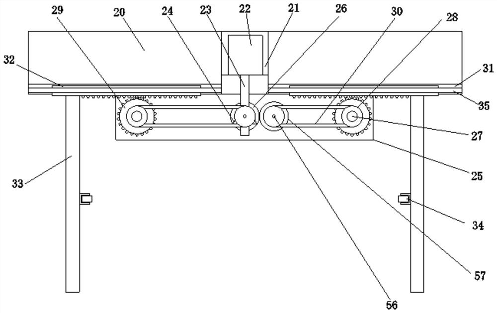
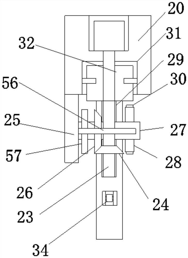
[0030] Embodiment one, by Figure 1 to Figure 5 Given, the present invention includes an emergency vehicle body 1, a compartment 2 is provided on the top of the emergency vehicle body 1, and a carbon dioxide storage tank 3 is provided inside the compartment 2, and the design of the carbon dioxide storage tank 3 facilitates the storage of carbon dioxide, thereby facilitating later fire extinguishing Operation, one side of the carbon dioxide storage tank 3 is provided with a connector 4, one side of the compartment 2 is movably connected with a movable box 5, and the side of the movable box 5 near the connector 4 is provided with an opening-6, and the bottom of the movable box 5 is opened There is an opening two 9, the inside of the movable box 5 is provided with a fire extinguishing mechanism 8 that runs through the opening two 9, one end of the connector 4 is connected with a connecting hose 7 that runs through the opening one 6 and is connected with the fire extinguishing mech...
Embodiment 2
[0035] Embodiment two, on the basis of embodiment one, by figure 1 and Figure 4 Given, the winding group comprises motor three 36, rotating shaft two 37 and winding wheel two 39, and motor three 36 is installed on the inner wall side of movable box 5, and the output shaft of motor three 36 is connected with rotating shaft two 37, and rotating shaft The second 37 is set with the second winding wheel 39 connected with the connecting rope 40. The connecting group includes the first winding wheel 38, the connecting pipe 44 and the clamper 45. The first winding wheel 38 is sleeved on the second rotating shaft 37. And the first winding wheel 38 is located on one side of the second winding wheel 39, the outer casing of the first winding wheel 38 is provided with a connecting pipe 44 connected to the connecting hose 7 and the installation shaft 42, and the connecting hose 7 and the connecting pipe 44 Connect by clamper 45 that is connected with winding wheel 1 38, rotator includes g...
Embodiment 3
[0037] Embodiment three, on the basis of embodiment one, by figure 1 , Figure 4 and Figure 5 Given, the clamp 45 includes a socket slot 50, a through hole 51, a fixing slot 52, a fixing rod 53, a spring 54 and a plug joint 55, and the connection hose 7 and the communication pipe 44 are connected through the plug joint 55, and the plug joint 55 is a T-shaped structure, and the outer wall of the first winding wheel 38 is provided with a socket slot 50 sleeved on one end of the plug connector 55, and one end of the plug connector 55 is provided with a through hole 51, and one side of the first winding wheel 38 is provided with a through hole 50. In the fixed groove 52 connected to the through hole 51 in the insertion groove 50, the inside of the fixed groove 52 is interspersed with a fixed rod 53 passing through the inside of the through hole 51. The spring 54 and the fixed rod 53 are T-shaped threaded rods, and the outer sleeve of the fixed rod 53 is provided with a stop rin...
PUM
 Abstract
Description
Claims
Application Information
 - R&D
- Intellectual Property
- Life Sciences
- Materials
- Tech Scout
- Unparalleled Data Quality
- Higher Quality Content
- 60% Fewer Hallucinations
Browse by: Latest US Patents, China's latest patents, Technical Efficacy Thesaurus, Application Domain, Technology Topic, Popular Technical Reports.
© 2025 PatSnap. All rights reserved.Legal|Privacy policy|Modern Slavery Act Transparency Statement|Sitemap|About US| Contact US: help@patsnap.com


