
Mobile robot

A mobile robot, rotating plate technology, applied in the field of mobile robots, can solve the problems of adjusting the travel direction, unable to perform cleaning mode, difficult to clean the ground meticulously, etc., to achieve the effect of miniaturization and accurate driving control

Pending Publication Date: 2022-03-11
LG ELECTRONICS INC
View PDF0 Cites 0 Cited by
  • Summary
  • Abstract
  • Description
  • Claims
  • Application Information

AI Technical Summary

Problems solved by technology

[0007] That is, the problems in the prior art are that it is difficult to supply water evenly from the water tank located in the main body to the mop attached to the rotating member without water leakage, and it is difficult to realize a structure that is easy to attach and detach.
[0008] In addition, in the prior art, since the sweeping robot travels only by the frictional force of the spin mop, and the water level of the water stored in the water tank is variable, it is not easy to perform mopping efficiently, and the driving force There is a problem with
[0009] In particular, since existing wet robots cannot easily adjust the direction of travel by friction with a rotating mop, there is a disadvantage that they can only perform cleaning in a random driving manner, and cannot perform pattern driving that can achieve meticulous cleaning.
[0010] In addition, the disadvantage of the existing technology is that it is not easy to meticulously clean the corners of the ground or the area adjacent to the wall when only random driving is performed

Method used


Image

  • Mobile robot
  • Mobile robot
  • Mobile robot

Examples


Embodiment Construction

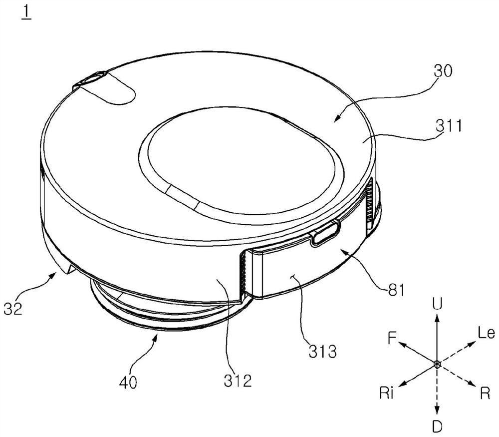
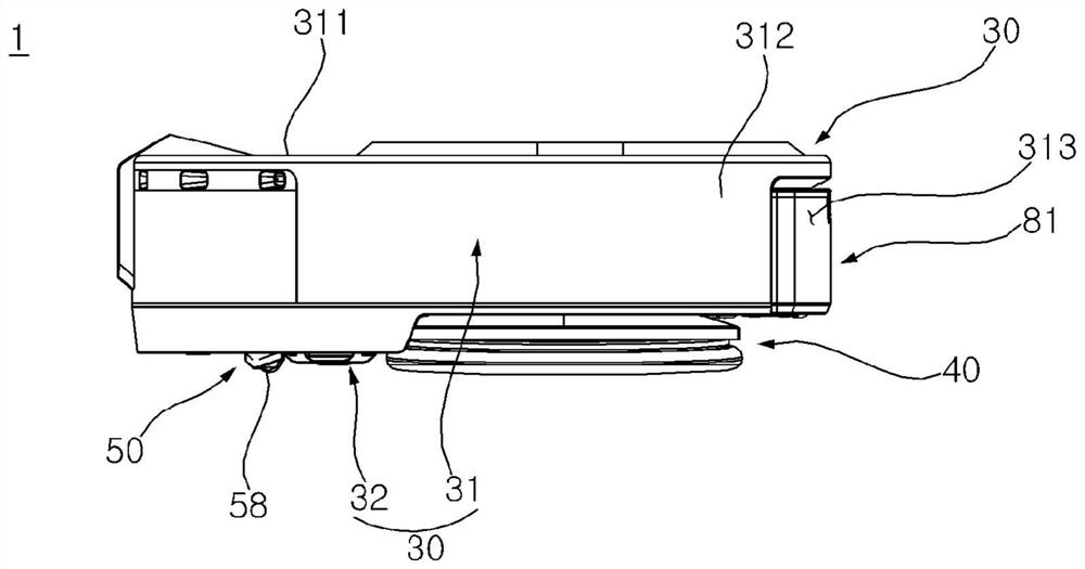
[0083] The expressions of "front F / rear R / left Le / right Ri / upper U / lower D" mentioned below are defined as shown in the figure, but this is only to illustrate the present invention and can be clearly understood. Of course, The various directions may be defined differently depending on the location of the fiducials.

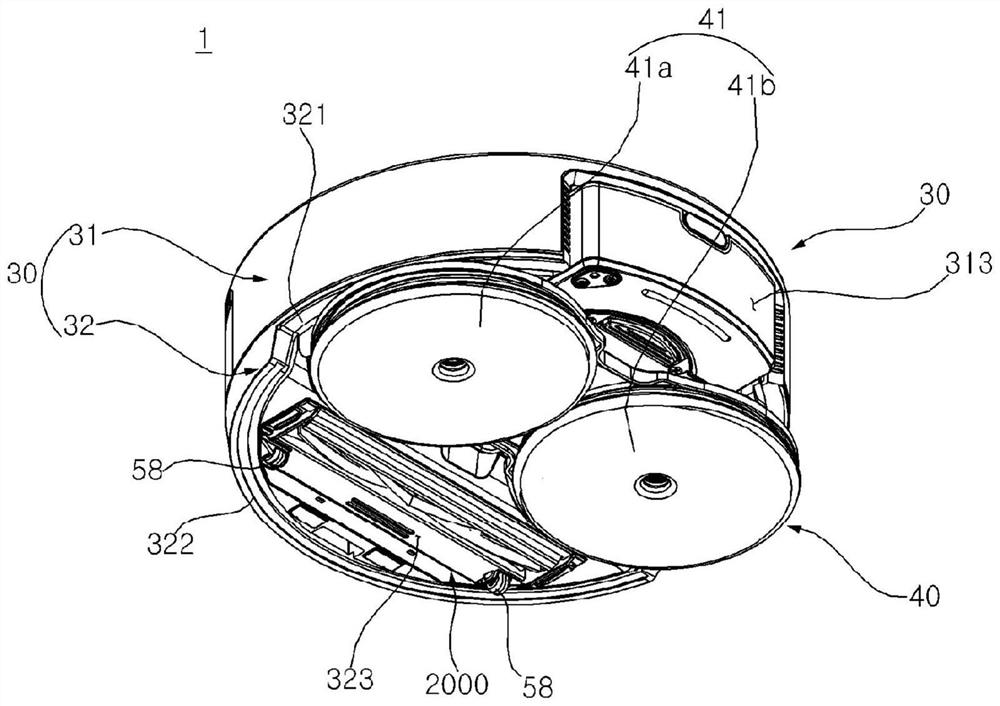
[0084] For example, define a direction parallel to an imaginary line connecting the central axis of the left-hand rotary mop and the central axis of the right-hand rotary mop as the left-right direction, and define a direction perpendicular to the left-right direction and parallel to the central axis of the rotary mop or an error angle A direction within 5 degrees is defined as an up-down direction, and a direction perpendicular to the left-right direction and the up-down direction is defined as a front-rear direction.

[0085] The use of terms such as "first, second, and third" before the structural elements mentioned below is only to avoid confusion about the st...


PUM


Abstract

The mobile robot according to the present invention comprises: a main body; the mop module comprises a left rotating plate and a right rotating plate which are rotatably arranged on the main body and are provided with a water supply space; a water supply distribution module which distributes and supplies water to the water supply space of the left rotating plate and the water supply space of the right rotating plate; and a water supply module for supplying water to the water supply distribution module, the water supply distribution module including: a water supply response unit connected to the water supply module and receiving water; a left water supply distribution pipe which is connected to the water supply response unit and supplies water from the water supply response unit to the water supply space of the left rotating plate; and a right side water supply distribution pipe connected to the water supply response part and supplying water from the water supply response part to the water supply space of the right side rotating plate, the length of the left side water supply distribution pipe being the same as the length of the right side water supply distribution pipe.

Description

technical field [0001] The invention relates to a mobile robot for mopping the ground. Background technique [0002] A mobile robot is a device that cleans by sucking impurities such as dust from the ground or wiping the impurities on the ground. More recently, mobile robots that can perform mopping are being developed. In addition, a mobile robot is a device that cleans while driving on its own. [0003] As prior art 1, a mobile robot capable of moving through a rag surface is disclosed. In the prior art, the first rotating member and the second rotating member of the mobile robot for fixing a pair of mopping surfaces arranged in the left and right directions are arranged with the vertical direction as the axis. The mobile robot in the prior art moves as the first rotating member and the second rotating member rotate when only the fixed rag surfaces on the first rotating member and the second rotating member are in contact with the ground. [0004] In the case of the pr...

Claims


Application Information

Patent Timeline
IPC IPC(8): B25J11/00B25J9/08B25J9/00A47L11/40
CPCA47L11/24A47L11/164A47L11/4083A47L11/4038A47L11/4041A47L11/4066A47L11/4069A47L2201/00A47L11/4088
Inventor 张宰源金荣彬李荣宰
Owner LG ELECTRONICS INC
Learn More