


Quick Research
Generate reliable direction feasibility study reports for your R&D in just a few steps.

Technical Q&A
Discover and master advanced knowledge NOW. Basics, ideas, possibilities, all at once.

Find Solutions
As an expert in R&D theories, this can generate solutions to your technical problems instantly.

Evaluate Feasibility
Analyze your overall solution with one click, know your potential R&D risks in advance.

Monitor Landscape
Get weekly tech updates, stay abreast of the latest tech innovations and key insights.
Sectional material component, sectional material and photovoltaic module frame
A technology for photovoltaic modules and profiles, applied in the fields of profiles, photovoltaic module frames, and profile components, can solve the problems of increasing the failure rate of modules, difficult to form convection, and accelerate the aging of components, so as to reduce the cost of raw materials and processing costs, good air convection and The effect of cycle, prolonging working life
- Summary
- Abstract
- Description
- Claims
- Application Information
AI Technical Summary
Problems solved by technology
Method used
Image

Examples
Embodiment 1
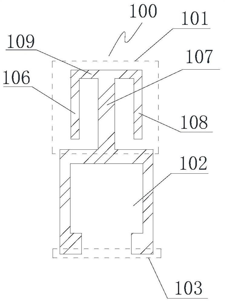
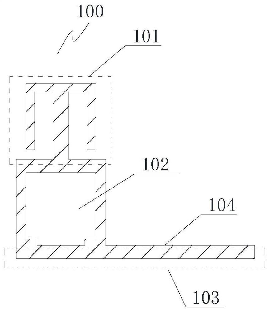
[0073] This embodiment provides a profile member 100, the profile member 100 is installed on the profile body 200 to form a profile 300; the profile component constitutes at least a part of the profile cavity. Preferably, the profile component 100 also forms the profile base 103 .
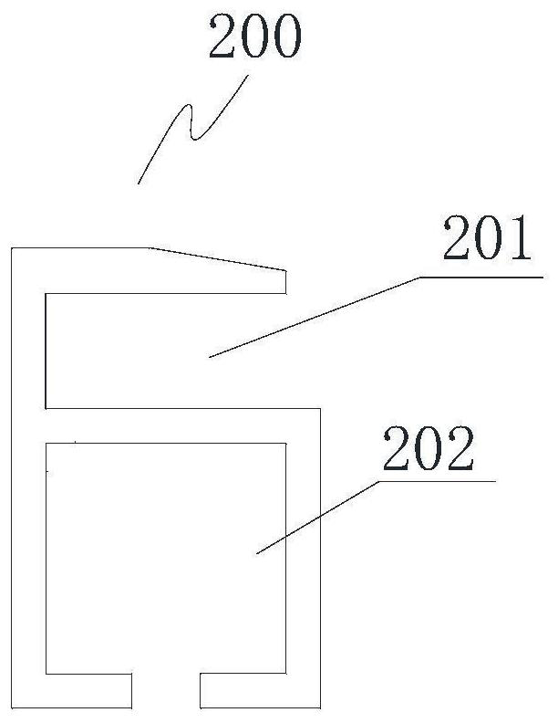
[0074] The profile body 200 has a bearing part for carrying the workpiece to be installed. In some specific embodiments, the bearing part is a notch 201, and the workpiece to be installed is installed in the notch; in other specific embodiments, the bearing The portion can also be in other shapes, such as a flat plate, and is not limited to the shape of the notch. The profile body 200 may also include a cavity for supporting the load-bearing portion, which is named as the first cavity 202 here.
[0075] Figure 1a A profile member 100 with a specific structure is shown. As shown in the figure, the profile member 100 has a connecting portion 101 connected to the profile body 200, and a second cavi...
Embodiment 2
[0085] Such as figure 2 As shown, this embodiment provides a profile member 100, and Figure 1b The difference between the profile members shown is that there are two second cavities 102, named here as the upper second cavity 102a and the lower second cavity 102b, and the two second cavities are located below the first cavity , not embedded in the second cavity. Two second die cavities are arranged horizontally, and the two second die cavities arranged horizontally are parallel to each other. The so-called "horizontally arranged" here means that the dimension on the width of the second cavity is larger than the dimension on its height
[0086] The profile member 100 is combined with the profile body 200 to form a corresponding profile. In this embodiment, the bottom edge of the lower second cavity 102b constitutes the bottom edge 103 of the profile. The bottom edge of the profile is the contact surface with the installation station.
Embodiment 3
[0088] Such as Figure 3a As shown, this embodiment provides a profile member 100, and Figure 1a The difference between the profile members shown is that: the profile member 100 is not embedded in the first cavity 202, and the profile component 100 is connected to the bottom edge of the first cavity 202 through the top edge of the second cavity 102. The specific connection method Can be glued or fastener connected.
[0089] Such as Figure 3b As shown, this embodiment provides a profile member 100, and Figure 1b The difference between the profile members shown is that: the profile member 100 is not embedded in the first cavity 202, and the profile component 100 is connected to the bottom edge of the first cavity 202 through the top edge of the second cavity 102. The specific connection method Can be glued or fastener connected.
[0090] As a modification, the profile body may not have a cavity, and the cavity of the profile is formed by the second cavity on the profile m...
PUM
| Property | Measurement | Unit |
|---|---|---|
| length | aaaaa | aaaaa |
| length | aaaaa | aaaaa |
| height | aaaaa | aaaaa |
Abstract
Description
Claims
Application Information
 - R&D Engineer
- R&D Manager
- IP Professional
- Industry Leading Data Capabilities
- Powerful AI technology
- Patent DNA Extraction
Browse by: Latest US Patents, China's latest patents, Technical Efficacy Thesaurus, Application Domain, Technology Topic, Popular Technical Reports.
© 2024 PatSnap. All rights reserved.Legal|Privacy policy|Modern Slavery Act Transparency Statement|Sitemap|About US| Contact US: help@patsnap.com