
Waste anesthetic gas extraction device for anesthesiology department

A waste gas and departmental technology, applied in gas treatment, steam condensation, dispersed particle filtration, etc., can solve problems such as fresh air treatment and purifier effect can not be completely extracted, health impact of medical staff, anesthesia gas leakage, etc., to improve condensation Effect, avoid uneven heating, good purification effect

Inactive Publication Date: 2022-03-11
衣美嫁(广州)贸易有限公司
View PDF0 Cites 0 Cited by
  • Summary
  • Abstract
  • Description
  • Claims
  • Application Information

AI Technical Summary

Problems solved by technology

[0002] Inhaled anesthesia drugs have been widely and effectively used in the induction and maintenance of general anesthesia in the operating room due to their advantages of anesthesia induction and rapid recovery. During the process, there will inevitably be a small amount of anesthesia waste gas emission due to leakage of the anesthesia machine, insufficient removal system, and patient exhalation. Although there have been many improvements in the safety of anesthesia equipment and anesthesia drugs, the leakage of anesthesia gas has a negative impact on the health of medical staff. have been under close clinical scrutiny
[0003] Existing anesthesia departments use the fresh air system in the room to remove the waste gas generated during the anesthesia process, or use an air purifier for treatment. The effect of treatment with the purifier cannot be completely removed, the purification effect is poor, and improvement is urgently needed

Method used


Image

  • Waste anesthetic gas extraction device for anesthesiology department
  • Waste anesthetic gas extraction device for anesthesiology department
  • Waste anesthetic gas extraction device for anesthesiology department

Examples


Embodiment Construction

[0028] The technical solutions in the embodiments of the present invention will be clearly and completely described below in conjunction with the accompanying drawings in the embodiments of the present invention. Obviously, the described embodiments are only some of the embodiments of the present invention, not all of them. In the present invention, terms such as "installation", "setting", "connection", "fixation" and "rotary connection" should be understood in a broad sense unless otherwise clearly specified and limited, for example, it can be a fixed connection or a It is a detachable connection, or integrated; it can be a mechanical connection or an electrical connection; it can be a direct connection or an indirect connection through an intermediary, it can be the internal communication of two components or the interaction relationship between two components, Unless otherwise clearly defined, those skilled in the art can understand the specific meanings of the above terms i...


PUM


Abstract

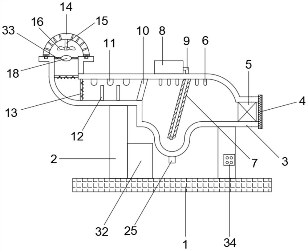
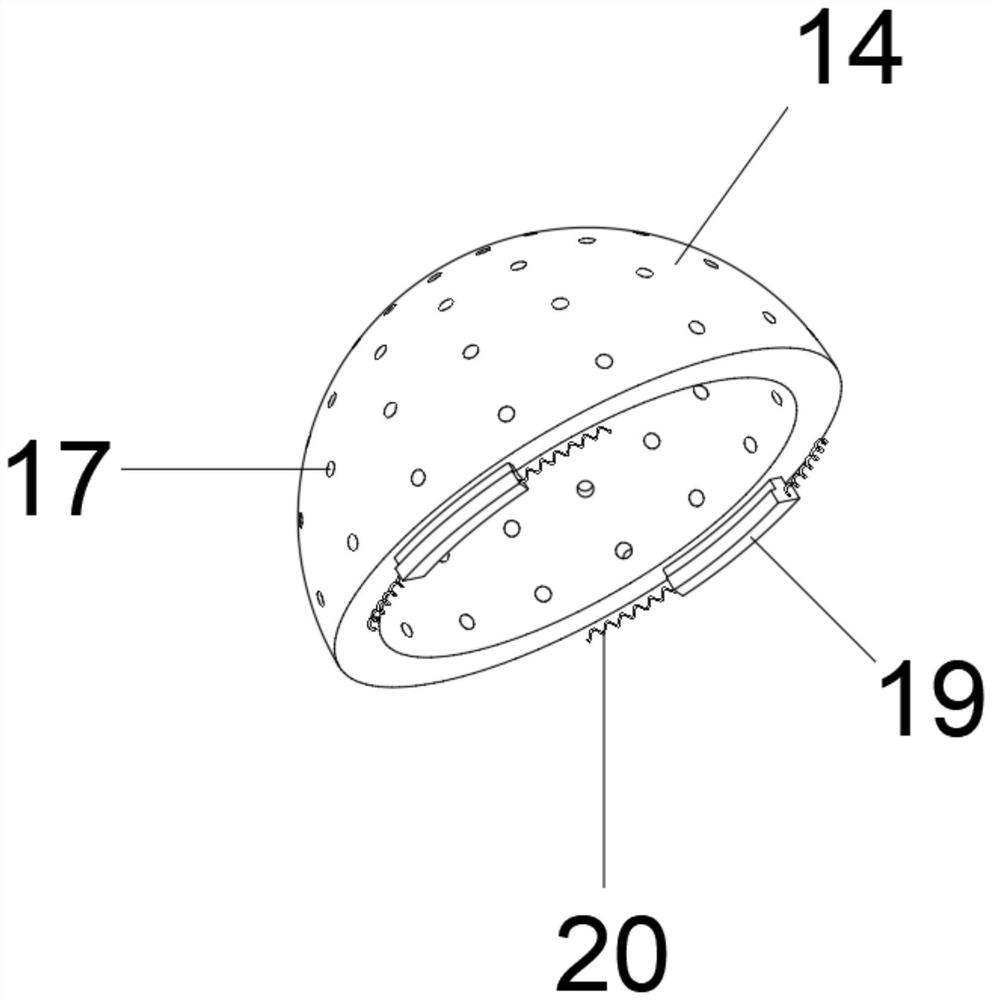
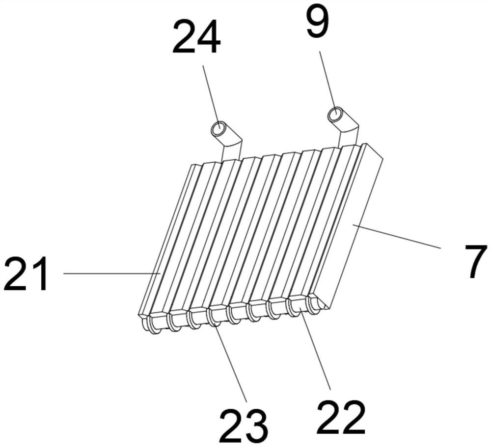
The waste anesthetic gas extraction device for the anesthesia department comprises a base and a shell, a supporting column is fixed to the outer wall of the top of the base through bolts, the shell is fixed to the outer wall of the top of the supporting column through bolts, and a storage battery is fixed to the outer wall of the top of the base through screws; a control panel is fixed to the outer wall of one side of the supporting column through screws, and a condensation plate is fixed to one side of the inner wall of the top of the shell through screws. According to the anesthesia device, through the arranged condensation plate, anesthetic medicine in anesthetic gas is liquefied when cooled and condensed into small water drops on the outer wall of the condensation plate, the small water drops flow to the outer wall of the semicircular ring after being collected through the triangular groove, the refrigeration effect is improved through the triangular groove, liquid can be conveniently collected and collected at the vertex of the semicircular ring, and finally the liquid falls into the arc-shaped inner wall of the shell; and the condensation effect of the anesthetic can be improved through the inclined plane design of the condensation plate, the removal effect of the anesthetic is improved, and the purification effect is good.

Description

technical field [0001] The invention relates to the technical field of anesthesia waste gas treatment, in particular to an anesthesia waste gas extraction device for an anesthesia department. Background technique [0002] Inhaled anesthesia drugs have been widely and effectively used in the induction and maintenance of general anesthesia in the operating room due to their advantages of anesthesia induction and rapid recovery. During the process, there will inevitably be a small amount of anesthesia waste gas emission due to leakage of the anesthesia machine, insufficient removal system, and patient exhalation. Although there have been many improvements in the safety of anesthesia equipment and anesthesia drugs, the leakage of anesthesia gas has a negative impact on the health of medical staff. effects have been closely monitored clinically. [0003] Existing anesthesia departments use the fresh air system in the room to remove the waste gas generated during the anesthesia...

Claims


Application Information

Patent Timeline
Patent Type & Authority Applications(China)
IPC IPC(8): B01D53/00A61L9/18B01D5/00B01D46/10B01D53/26
CPCB01D53/002B01D53/261B01D46/10A61L9/18B01D5/0072B01D2257/80
Inventor 杨士玉曹一陈闪
Owner 衣美嫁(广州)贸易有限公司
Learn More