Filling structure for airtight test
A technology of air tightness test and filling body, which is applied in the direction of using liquid/vacuum degree for liquid tightness measurement, etc., can solve the problem that the filling body is not easy to be filled, and achieve the effect of convenient filling, not easy to damage, and improving the pressure bearing capacity.
- Summary
- Abstract
- Description
- Claims
- Application Information
AI Technical Summary
Problems solved by technology
Method used
Image
Examples
Embodiment 1
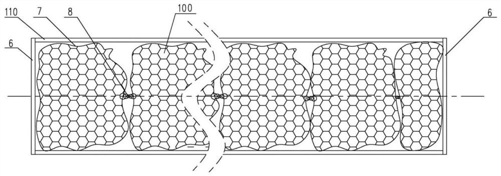
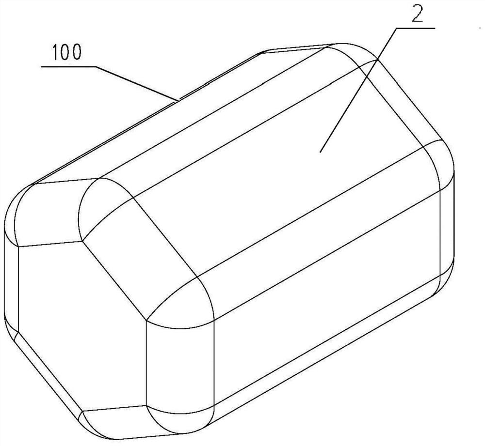
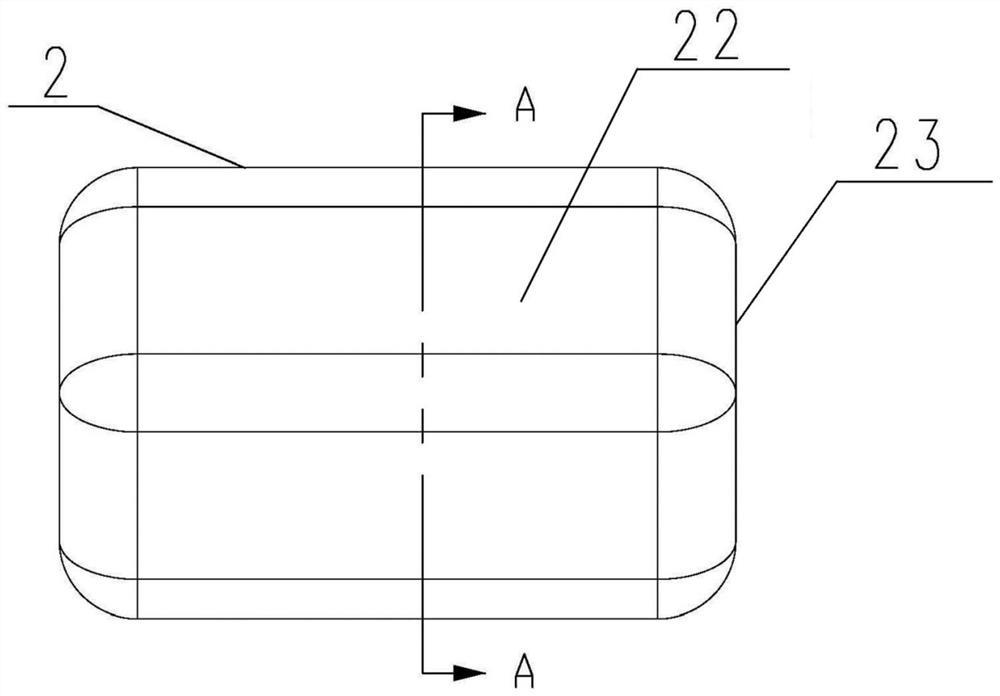
[0049] The filling body 100 used in the gas sealing test in the prior art is a large-scale tooling designed in one piece, and its shape is only suitable for testing tanks of corresponding shapes. If it is necessary to perform leak detection on other shells, it needs to be redesigned. The filling body 100 adapted to the casing has high cost, and the versatility of the filling body 100 is poor, and the mass of the large-scale tooling is relatively large, making it difficult to fill. The filling structure for the airtight test provided by the present invention divides and miniaturizes the filling body 100, and each filling body 100 can be magnetically attracted to each other, and a plurality of filling bodies 100 are magnetically attracted to form a filling group. Blocks, each packing block is contained by the net bag 7, and connected in series by the connecting hinge 8, so as to be convenient to fill in the airtight cavity 110 to be tested as a filler, so as to fully occupy the i...
Embodiment 2
[0061] The main difference between it and Embodiment 1 is that in Embodiment 1, the weight reducing cavity 21 is hollow. In this embodiment, when the strength of the material forming the pressure-resistant casing 2 is not high enough, such as Figure 5 As shown, the lightweight filler 3 needs to be filled in the weight-reducing cavity 21. Specifically, the lightweight filler can be ceramsite, mineral wool, asbestos, polyester foam, etc., and the lightweight filler 3 is filled with the pressure-resistant shell 2. The cavity 21 is heavy to increase the overall strength of the filling body 100 .
Embodiment 3
[0063] The main difference between it and the embodiment 2 is that in the embodiment 2, the light weight filler 3 is filled in the weight reduction cavity 21 to increase the strength of the filler body 100 . In this example, if Image 6 As shown, a supporting frame 4 is provided in the weight-reducing cavity 21 of the pressure-resistant housing 2 , and the supporting frame 4 is supported and connected with the pressure-resistant housing 2 in the weight-reducing cavity 21 to increase the overall strength of the filling body 100 .
[0064] In actual implementation, the pressure-resistant shell 2 can be arranged in half. At this time, the weight-reducing cavity 21 is also set in half in the two-and-a-half pressure-resistant shell 2, and the support frame 4 is first filled into the two-and-a-half pressure-resistant shell. 2 in the weight-reducing cavity 21 of one of them, and then the two and a half pressure-resistant shells 2 are fastened and spliced together, so that the suppo...
PUM
 Abstract
Description
Claims
Application Information
 - Generate Ideas
- Intellectual Property
- Life Sciences
- Materials
- Tech Scout
- Unparalleled Data Quality
- Higher Quality Content
- 60% Fewer Hallucinations
Browse by: Latest US Patents, China's latest patents, Technical Efficacy Thesaurus, Application Domain, Technology Topic, Popular Technical Reports.
© 2025 PatSnap. All rights reserved.Legal|Privacy policy|Modern Slavery Act Transparency Statement|Sitemap|About US| Contact US: help@patsnap.com


