Turbine outer ring connection assembly, gas turbine engine and connection method

A technology for connecting components and connecting parts, which is applied in the direction of engine components, machines/engines, mechanical equipment, etc., can solve problems such as vibration bumps, scratches between outer ring parts and rotor blade tips, and damage to rotor blades, so as to facilitate installation and reduce The effect of increasing the amount of cooling gas and the upper limit of temperature

Active Publication Date: 2022-03-08
AECC COMML AIRCRAFT ENGINE CO LTD
View PDF5 Cites 0 Cited by
  • Summary
  • Abstract
  • Description
  • Claims
  • Application Information

AI Technical Summary

Problems solved by technology

In the prior art, in order to solve the problem of thermal deformation mismatch, a technical solution is adopted to reserve a gap in the connection and installation structure between the CMC turbine outer ring component and the metal parts of the engine during cold installation, but the inventors found that such an arrangement would lead to The problem of vibration and bumping
[0005] At the same time, the gap between the outer ring and the turbine rotor blades is small. When the engine generates abnormal unbalanced load or vibration, it is easy to scratch the outer ring and the tip of the rotor blade.
However, the hardness of ceramic matrix composite material is relatively high. If the outer ring of ceramic matrix composite material is used, once the friction between the outer ring and the rotor blade occurs, the damage of the outer ring of ceramic matrix composite material to the rotor blade will be greater than that of the traditional metal outer ring. ring is more serious

Method used


Image

  • Turbine outer ring connection assembly, gas turbine engine and connection method
  • Turbine outer ring connection assembly, gas turbine engine and connection method
  • Turbine outer ring connection assembly, gas turbine engine and connection method

Examples


Embodiment Construction

[0029] A variety of different implementations or examples for implementing the described subject technical solutions are disclosed below. In order to simplify the disclosure, the following describes the specific examples of each component and arrangement, of course, these are only examples, not limiting the protection scope of the present invention.

[0030] In addition, the "axial", "circumferential", "radial", "inner" and "outer" that may be involved in the following embodiments are relative to the outer ring of the turbine.

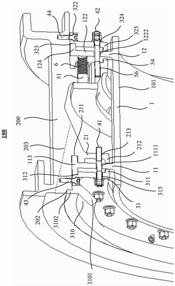
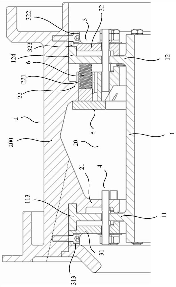
[0031] refer to Figure 1A , Figure 1B , figure 2 as well as image 3, the turbine outer ring connection assembly 100 includes a turbine outer ring extension 10 and a mounting assembly 20 . The turbine outer ring extension 10 extends radially outward from the turbine outer ring body 1 , and includes an axially adjacent upstream mounting portion 11 and a downstream mounting portion 12 . The upstream mounting part 11 includes a first rib 111 and a ...


PUM


Abstract

The invention relates to a turbine outer ring connecting assembly, a gas turbine engine and a connecting method. The turbine outer ring connecting assembly comprises a turbine outer ring extending piece, the turbine outer ring extending piece comprises an upstream installation part and a downstream installation part which extend outwards in the radial direction of a turbine outer ring body and are adjacent in the axial direction, and the upstream installation part comprises a first rib plate and a first axial extending body extending towards the two axial sides from the first rib plate; the downstream mounting part comprises a second rib plate and a second axial extension body extending from the second rib plate to one axial side; and the first rib plate and the second rib plate are respectively provided with a first mounting hole and a second mounting hole. The mounting assembly comprises a middle bearing case, and the middle bearing case comprises a middle bearing case body and a first mounting part extending inwards from the body in the radial direction; the pressing piece comprises a first pressing piece and a second pressing piece; the connecting piece comprises a first connecting piece and a second connecting piece; an elastic piece and a mounting seat.

Description

technical field [0001] The invention relates to the field of gas turbine engines, in particular to a turbine outer ring connection assembly, a gas turbine engine and a connection method. Background technique [0002] Components of gas turbines often need to withstand extremely high temperatures, such as the outer ring of the turbine, which is the main turbine stationary part of the gas turbine, and it is subjected to a high ambient temperature in service. At present, the turbine outer ring components are mainly made of superalloy materials, but the strength and stiffness of the superalloy materials will decrease significantly under high temperature environment, which will affect the upper limit of the service temperature of the turbine outer ring components, and ultimately limit the overall performance of the gas turbine engine. [0003] The use of ceramic matrix composites (Ceramic Matrix Composite, CMC) instead of superalloy materials to prepare gas turbine engine turbine ...

Claims


Application Information

Patent Timeline
Patent Type & Authority Applications(China)
IPC IPC(8): F01D25/24F01D9/04
CPCF01D25/24F01D25/246F01D25/243F01D25/005F01D9/04F05D2300/6033Y02T50/60
Inventor 罗莉胡寿丰郭洪宝洪智亮李开元
Owner AECC COMML AIRCRAFT ENGINE CO LTD
Why Eureka
Try Eureka