Integrated multi-channel injection device suitable for microfluidic device
A technology of injection device and fluid channel, applied in the field of integrated micro-injection pump, can solve the problems of difficulty in moving and arranging the equipment, the relative position of the pump and the device is not fixed, difficult to move and arrange, etc. Moving and deploying, limiting and small footprint effects
Active Publication Date: 2022-03-08
EAST CHINA UNIV OF SCI & TECH
View PDF16 Cites 0 Cited by
- Summary
- Abstract
- Description
- Claims
- Application Information
AI Technical Summary
Problems solved by technology
As shown in the patent CN204709525U, the integrated micro-injection pump encapsulates the actuator and controller that complete the injection action in the same housing to form an independent device. Although it can have multiple syringe channels, it often uses the same push plate for injection. Achieve independent control of multiple channels, and microfluidic systems often require independent control of multiple fluids, so when using an integrated micro-injection pump for microfluidic experiments, it often requires the use of multiple devices, which will occupy a large amount of operating space And it is cumbersome to control multiple syringe pumps separately
As shown in the patent CN208389094U, the split-type micro-injection pump is divided into two parts: the controller and the actuator, which are connected by power / data lines. One controller can be connected with multiple actuators to realize multiple independent syringes. The control of the channel, but the relative position between the controller and the actuator is not fixed, and special fixtures are required for fixing, and the movement and arrangement of the equipment are difficult
The two types of micro-injection pumps are connected to the microfluidic devices with flexible tubes. The relative positions of the pumps and the devices are not fixed, so it is difficult to move and arrange, and it is difficult to provide a relatively clean environment for micro-reactions.
Method used
View moreImage
Smart ImageViewing Examples
Examples
Embodiment
[0030] Implementation example: Experiment of preparing core-shell structure encoded microspheres by microfluidic method, the specific content is as follows:
Login to View More PUM
 Abstract
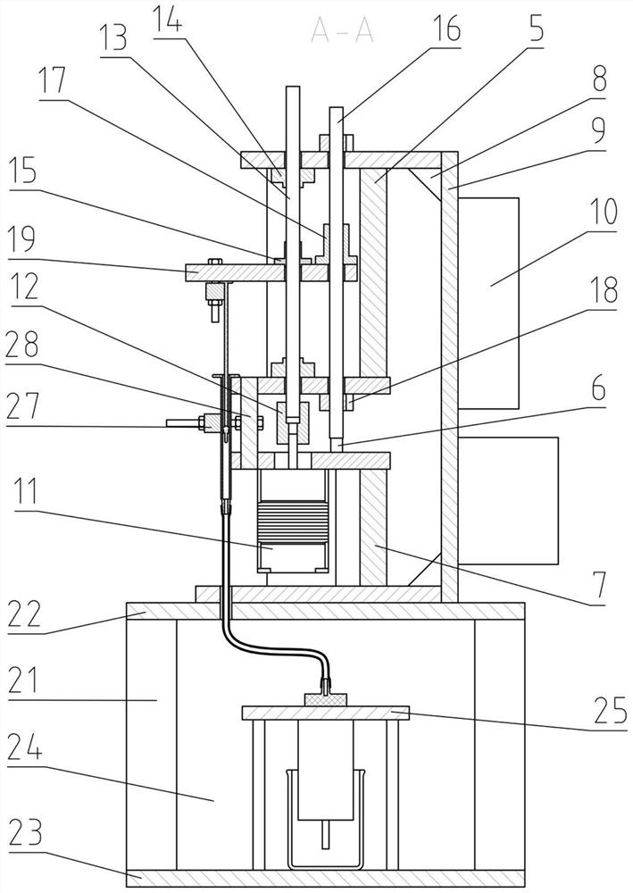
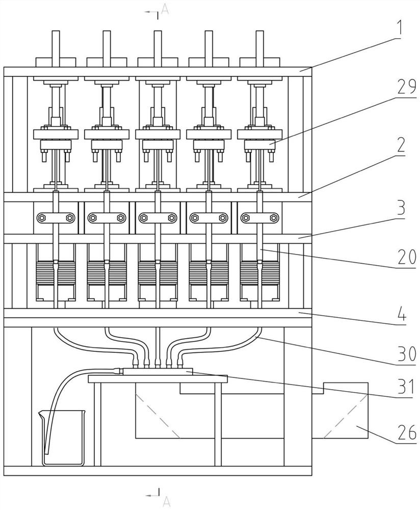
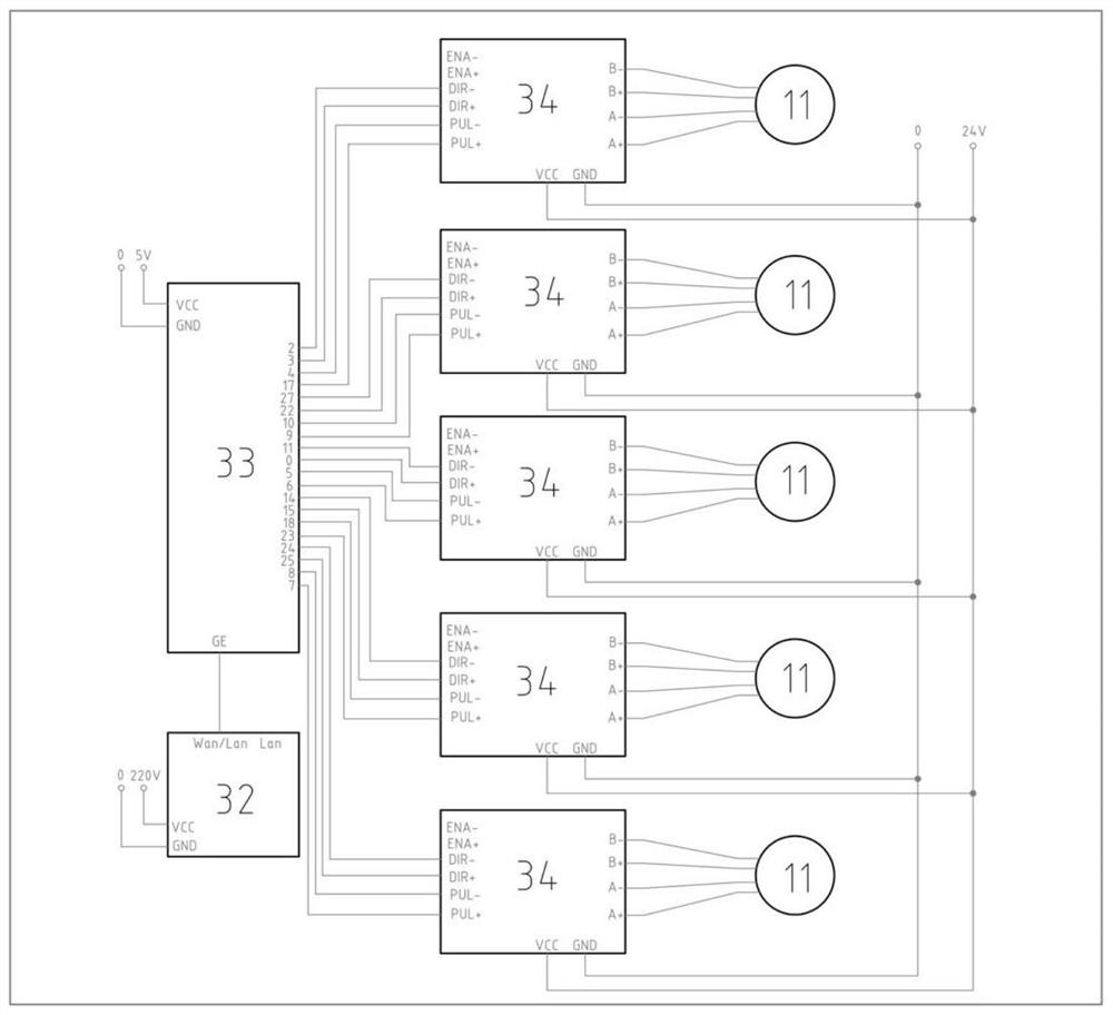
The invention relates to an integrated multi-channel injection pump suitable for a microfluidic device. The integrated multi-channel injection pump comprises an upper injection pump mechanical structure and a lower closed chamber, aiming at the requirements of a microfluidic device on a plurality of independent fluid channels and a relatively clean working environment, the upper injection pump mechanical structure is provided with a plurality of fluid channels which can be independently controlled; and the lower closed chamber is isolated from the outside through a transparent plate and is provided with a periscope, so that liquid flow in the microfluidic device can be observed from the outside of the closed chamber. According to the invention, a fluid driving subsystem and a microfluidic device are integrated into a set of compact equipment, so that integral movement and arrangement can be conveniently carried out, and the limitation and occupation of an experiment site are smaller. Synchronous remote control can be conveniently carried out on a plurality of channels through the upper computer, and one power line is used for supplying power to all electrical components, so that the experiment operation is more convenient.
Description
technical field [0001] The invention relates to the design field of an integrated micro-injection pump, and designs an integrated micro-injection pump with multiple independent channels. The invention is especially suitable for the requirements of microfluidic devices for precise and individual control of multiple fluids and the requirements of microreactions for clean spaces, and its application relates to the field of microfluidic technology. Background technique [0002] Microfluidic technology refers to the technology of controlling micro-liquids with a volume of nanoliters to attoliters in microchannels with a scale of tens to hundreds of microns. It has been extensively researched and developed since it was proposed in the 1960s and 1970s. . At present, microfluidic technology has been widely used in real-time detection, biochemical analysis, chemical synthesis and other fields due to its characteristics of high throughput, integration, and miniaturization. A microfl...
Claims
Login to View More Application Information
Patent Timeline
 Patent Type & Authority Applications(China)
IPC IPC(8): B01L3/00
CPCB01L3/50273B01L2400/0475
Inventor 栾伟玲孙敏张嘉寅毛可欣肖伟铜
Owner EAST CHINA UNIV OF SCI & TECH
Features
- R&D
- Intellectual Property
- Life Sciences
- Materials
- Tech Scout
- Unparalleled Data Quality
- Higher Quality Content
- 60% Fewer Hallucinations
Learn More Browse by: Latest US Patents, China's latest patents, Technical Efficacy Thesaurus, Application Domain, Technology Topic, Popular Technical Reports.
© 2025 PatSnap. All rights reserved.Legal|Privacy policy|Modern Slavery Act Transparency Statement|Sitemap|About US| Contact US: help@patsnap.com


