Debugging jig and debugging method

A debugging method and jig technology, applied in educational tools, transportation and packaging, measuring devices, etc., can solve the problems of energy consumption and low accuracy, and achieve the effect of reducing energy consumption, smooth debugging and high accuracy

Pending Publication Date: 2022-03-04
AMBULANC (SHENZHEN) TECH CO LTD
View PDF0 Cites 0 Cited by
  • Summary
  • Abstract
  • Description
  • Claims
  • Application Information

AI Technical Summary

Problems solved by technology

However, in the existing structure, there is no tooling for debugging the sensor. It is necessary to use tools such as a ruler to manually keep the sensor fixed at a certain position for debugging, which is low in accuracy and consumes a lot of energy.

Method used


Image

  • Debugging jig and debugging method
  • Debugging jig and debugging method
  • Debugging jig and debugging method

Examples


Embodiment Construction

[0046] The following will clearly and completely describe the technical solutions in the embodiments of the present invention with reference to the accompanying drawings in the embodiments of the present invention. Obviously, the described embodiments are only part of the embodiments of the present invention, not all of them. Based on the embodiments of the present invention, all other embodiments obtained by persons of ordinary skill in the art without creative efforts fall within the protection scope of the present invention.

[0047] It should be noted that all directional indications (such as up, down, left, right, front, back...) in the embodiments of the present invention are only used to explain the relationship between the components in a certain posture (as shown in the accompanying drawings). Relative positional relationship, movement conditions, etc., if the specific posture changes, the directional indication will also change accordingly.

[0048] In the present in...


PUM


Abstract

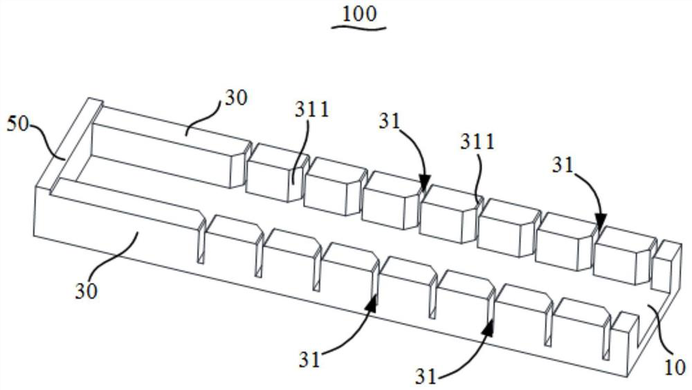
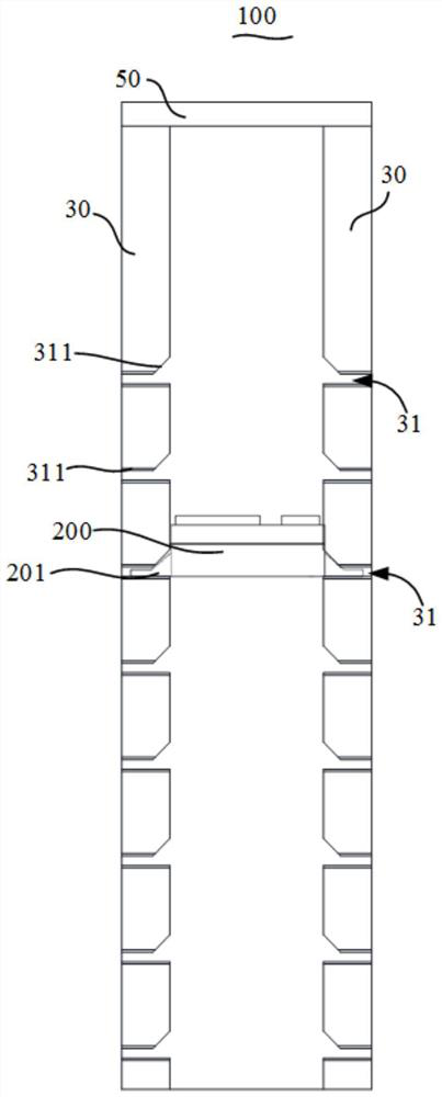
The invention discloses a debugging jig and a debugging method.The debugging jig is used for debugging a distance sensor in a model person, the debugging jig comprises a base, a fixing piece and a reflecting plate, the fixing piece is arranged on the base, and the fixing piece is provided with a fixing part for fixing the distance sensor; and the reflecting plate is arranged on the base, is spaced from the fixing part by a first preset distance, and is used for reflecting emitted light of the distance sensor. According to the technical scheme, the debugging jig can conveniently debug the distance sensor, time and labor are saved, and the adjusting precision is high.

Description

technical field [0001] The invention relates to the technical field of debugging devices, in particular to a debugging jig and a debugging method using the debugging jig. Background technique [0002] For purposes such as teaching, a model man is usually used to practice cardiopulmonary resuscitation, and in the process of cardiopulmonary resuscitation, compression depth is an extremely important parameter. Generally, an infrared distance sensor will be set in the model man to detect the compression depth in real time, so that information such as whether the cardiopulmonary resuscitation operation is standardized can be fed back. [0003] In order to ensure the accuracy of the detection, the infrared distance sensor and the control board will be installed in the model man after debugging. However, in the existing structure, there is no tooling for debugging the sensor. It is necessary to use tools such as a ruler to manually keep the sensor fixed at a certain position for d...

Claims


Application Information

Patent Timeline
Patent Type & Authority Applications(China)
IPC IPC(8): G09B9/00G01C3/00G01C25/00
CPCG09B9/00G01C3/00G01C25/00
Inventor 高超谢荣锋王瑞强张晓华
Owner AMBULANC (SHENZHEN) TECH CO LTD
Why Eureka
Try Eureka