
Explosion door of micro-positive pressure flue gas and air system

An explosion-proof door, micro-positive pressure technology, applied in safety valves, engine components, balance valves, etc., can solve problems such as difficulty in high-altitude operations, increased safety risks, increased maintenance workload, and difficulty in disassembling flange bolts. The effect of simplifying the maintenance operation process and operation difficulty, controlling operation risks, and reducing the frequency of occurrence

Pending Publication Date: 2022-03-04
西安沣东华能热力有限公司
View PDF0 Cites 0 Cited by
  • Summary
  • Abstract
  • Description
  • Claims
  • Application Information

AI Technical Summary

Problems solved by technology

The installation, fixing and sealing of diaphragm type explosion-proof door bursting discs are most commonly clamped by matching flanges, fastening bolts and gaskets, and are generally recognized and widely used in the market due to their simple structure and low cost. However, when the diaphragm explosion-proof door is used in the open air or in a corrosive environment for a long time, the corrosion of the flange bolts will make it difficult to disassemble the flange bolts, difficult to replace the blasting components, and the maintenance workload will increase accordingly. Under some working conditions and installation conditions (the gravity type or constant pressure automatic opening and closing type explosion-proof doors are not applicable), if the installation position of the explosion-proof door is relatively high, and the blasting components on it need to be replaced frequently, then in this state The difficulty and safety risks of high-altitude operations will increase significantly

Method used


Image

  • Explosion door of micro-positive pressure flue gas and air system
  • Explosion door of micro-positive pressure flue gas and air system
  • Explosion door of micro-positive pressure flue gas and air system

Examples


Embodiment 1

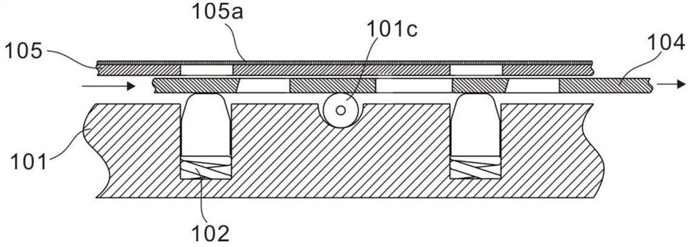
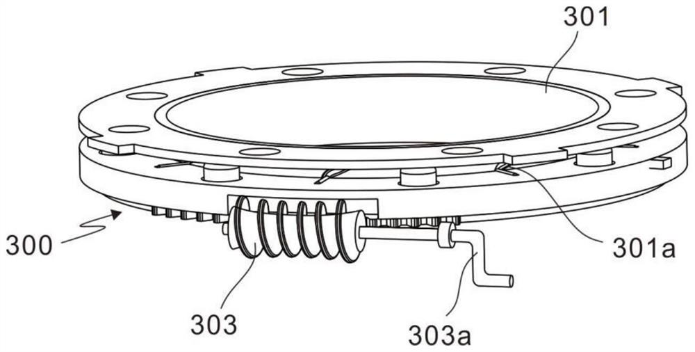
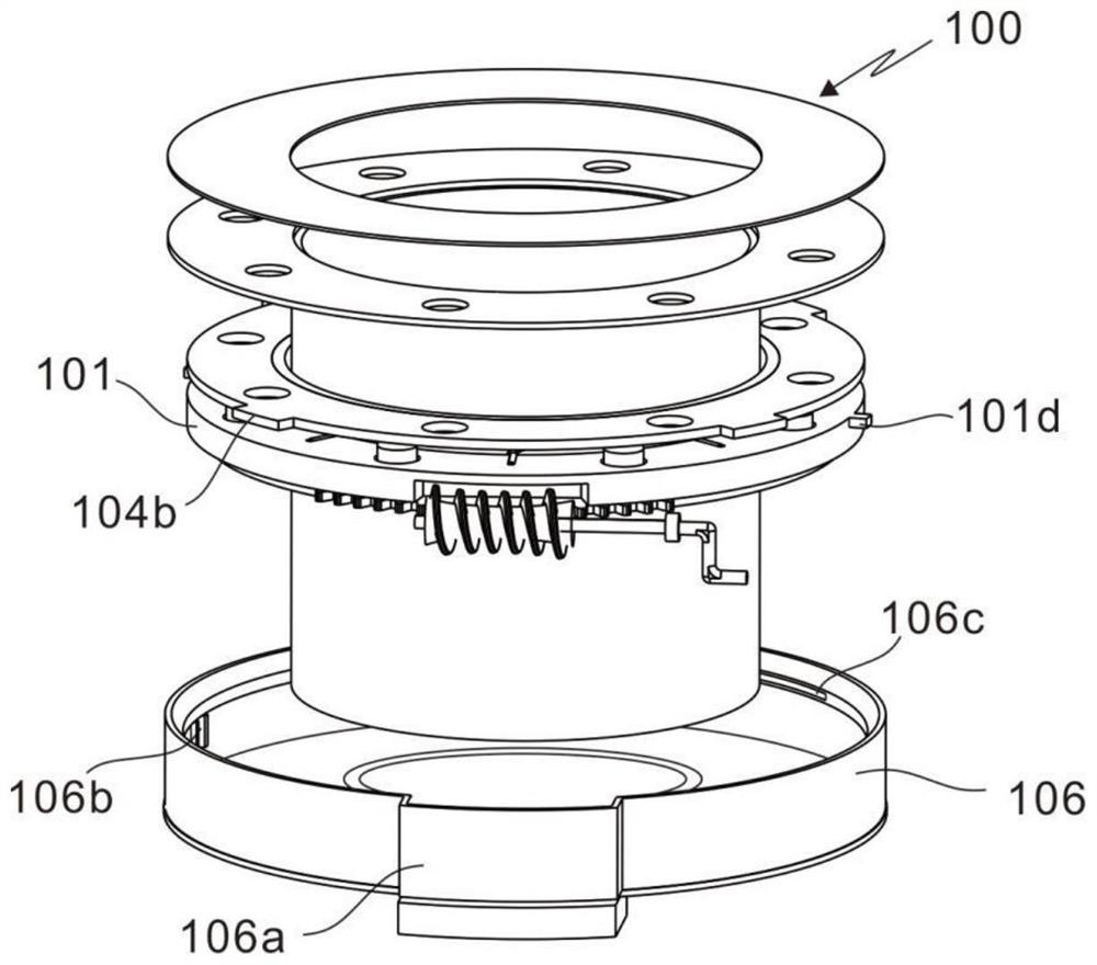
[0028] refer to Figure 1 ~ Figure 3 , which is the first embodiment of the present invention, this embodiment provides a kind of explosion-proof door of the micro-positive pressure smoke system, and the explosion-proof door of the micro-positive pressure smoke system includes a sealing assembly 100 and a blasting element 200 .

[0029] Specifically, the sealing assembly 100 includes a bottom plate 101, a spring 102, permanent magnet particles 103, and a silicon steel sheet 104. The bottom plate 101 is an annular thick steel plate with a circular groove 101a on the surface. The spring 102 is arranged in the circular groove 101a, and the permanent magnet The particles 103 are arranged above the spring 102 to absorb the blasting element 200. The silicon steel sheet 104 is ring-shaped and arranged above the bottom plate 101, which can shield or release the magnetism of the permanent magnet particles, so that the replacement of the old blasting element and the sealing surface The ...

Embodiment 2

[0032] refer to Figure 1 ~ Figure 4 , is the second embodiment of the present invention, which is based on the previous embodiment.

[0033] Concretely, on the semiperimeter arc length where the first through hole 104a of the silicon steel sheet 104 is in contact with the permanent magnet particle 103, a tapered surface is made along the thickness direction of the silicon steel sheet 104, and the taper of its projection is consistent with the taper at the top of the permanent magnet particle 103 , when the silicon steel sheet 104 rotates and moves, there is a downward pressure on the permanent magnetic particle 103 on the conical surface, so that the permanent magnetic particle 103 compresses the spring 102 in the circular groove 101a, and the part is received in the circular groove 101a, and the silicon steel sheet 104 The first through hole 104a passes through the permanent magnetic particles 103 smoothly, and shields the permanent magnetic particles 103 magnetically.

[0...

Embodiment 3

[0040] refer to Figure 3 ~ Figure 6 , is the third embodiment of the present invention, which is based on the first two embodiments.

[0041] Specifically, the sealing assembly 100 further includes a cover plate 105 and a housing 106 . The cover plate 105 is an annular thin steel plate, and its surface is provided with second through holes 105a which are consistent with the number of circular grooves 101a and the center distance of the holes. The surface of the cover plate 105 is provided with a rubber lining layer 105b, and the permanent magnetic particles 103 pass through the first through holes. 104a and the second through hole 105a absorb the blasting element 200, and the thickness of the rubber lining layer 105b is moderate, and its thickness range can take into account both magnetic permeability and sealing performance, and is made of fluororubber material with high temperature resistance, aging resistance and corrosion resistance; and, the shell 106 is disposed on the...


PUM


Abstract

The invention discloses an explosion door of a micro-positive-pressure flue gas and air system. The explosion door comprises a sealing assembly, an explosion element, a rotating assembly and a matching assembly. The sealing assembly comprises a bottom plate, springs, permanent magnet particles, silicon steel sheets, a cover plate and a shell. The rotating assembly comprises a connecting ring, a turbine and a worm; the matching assembly comprises a valve cover, a hinge, a hasp and a pipe connecting seat. According to the device, the permanent magnet is embedded in the sealing assembly to attract and position the blasting element, the blasting element does not need to be tailed during manufacturing, the mounting position of the blasting element can be freely adjusted through the magnetic switching action in the opening state of the anti-explosion door valve cover, manufacturing, mounting and position adjusting of the blasting element are simpler and more convenient, and the practicability is high. And the embedded silicon steel sheet with the holes can shield or release the magnetism of the permanent magnet particles, so that the replacement of the old blasting element and the cleaning work of the sealing surface are simpler and easier.

Description

technical field [0001] The invention relates to the field of explosion-proof technology, in particular to an explosion-proof door for a micro-positive pressure smoke and wind system. Background technique [0002] At present, the safety relief devices on the smoke and air ducts of active industrial boilers and some medium and low pressure containers usually choose fracture safety relief devices, that is, diaphragm explosion-proof doors, in the design and selection. This type of safety pressure relief device breaks and discharges gas through the bursting element (bursting disc) under high pressure, so that the pressure pipe or container is quickly released, thereby achieving the protection of the pressure pipe or container. The installation, fixing and sealing of diaphragm type explosion-proof door bursting discs are most commonly clamped by matching flanges, fastening bolts and gaskets, and are generally recognized and widely used in the market due to their simple structure a...

Claims


Application Information

Patent Timeline
Patent Type & Authority Applications(China)
IPC IPC(8): F16K17/16
CPCF16K17/16
Inventor 张涛
Owner 西安沣东华能热力有限公司
Learn More