


Quick Research
Generate reliable direction feasibility study reports for your R&D in just a few steps.

Technical Q&A
Discover and master advanced knowledge NOW. Basics, ideas, possibilities, all at once.

Find Solutions
As an expert in R&D theories, this can generate solutions to your technical problems instantly.

Evaluate Feasibility
Analyze your overall solution with one click, know your potential R&D risks in advance.

Monitor Landscape
Get weekly tech updates, stay abreast of the latest tech innovations and key insights.
Testing device for testing buffering performance of hydraulic buffering oil cylinder and testing method thereof
A technology of hydraulic buffer and test device, which is applied in the direction of fluid pressure actuation device, fluid pressure actuation system test, mechanical equipment, etc. Improve the effectiveness of test coverage
- Summary
- Abstract
- Description
- Claims
- Application Information
AI Technical Summary
Problems solved by technology
Method used
Image

Examples
Embodiment 1
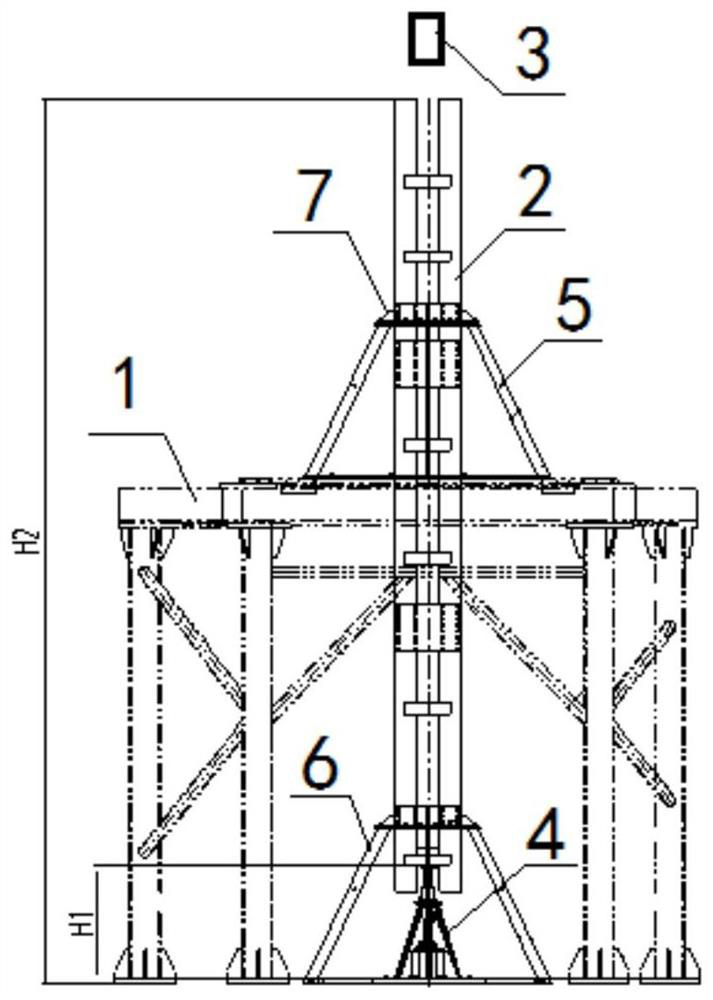
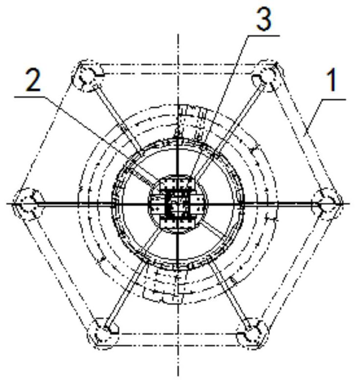
[0054] A test device for testing the buffer performance of a hydraulic buffer cylinder, the test device includes: a bench 1, a guide device 2, a counterweight vehicle 3 and a measuring device 4; the central axis of the bench 1 is pierced with a guide device 2 , the guide device 2 is arranged in the vertical direction, a measuring device 4 is arranged directly below the guide device 2, and the installation position of the hydraulic buffer cylinder 8 to be tested is arranged inside the measuring device 4, and the inner wall of the guide device 2 is in contact with the The side elevation of the counterweight truck 3 is slidingly fitted; the measuring device 4 includes a coaxially arranged installation base plate 41, a tapered bracket 42, an oil cylinder installation bracket 43, a guide cylinder 44, a pressure sensor 45 and a guide rod 46, and the installation The top of the base plate 41 is fixedly connected with the bottom of the oil cylinder mounting bracket 43. A hydraulic buff...
Embodiment 2
[0060] Embodiment 2 is basically the same as Embodiment 1, and its difference is:
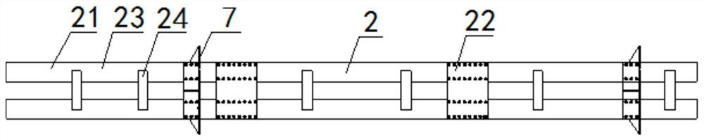
[0061] The segmented guide cylinder 21 includes two guide rails 23 and a plurality of transverse connecting plates 24 , the two guide rails 23 are arranged opposite to each other, and both sides of the two guide rails 23 are connected by the transverse connecting plates 24 .
Embodiment 3
[0063] Embodiment 3 is basically the same as Embodiment 2, and its difference is:
[0064] The counterweight truck 3 includes a flat counterweight 31, an H-shaped wheel seat 32, two auxiliary wheels 33 and a plurality of casters 34, and an H-shaped wheel seat 32 is respectively fixed on the top and bottom of the flat counterweight 31 Two casters 34 are respectively fixed on the outer sides of the two flanges of the H-shaped wheel seat 32, and the casters 34 are slidably matched with the guide rail 23, and one auxiliary wheel is respectively fixed on both sides of the web of the H-shaped wheel seat 32 33, the auxiliary wheel 33 is slidingly matched with the vertical connecting plate 22 and the transverse connecting plate 24.
PUM
 Abstract
Description
Claims
Application Information
 - R&D Engineer
- R&D Manager
- IP Professional
- Industry Leading Data Capabilities
- Powerful AI technology
- Patent DNA Extraction
Browse by: Latest US Patents, China's latest patents, Technical Efficacy Thesaurus, Application Domain, Technology Topic, Popular Technical Reports.
© 2024 PatSnap. All rights reserved.Legal|Privacy policy|Modern Slavery Act Transparency Statement|Sitemap|About US| Contact US: help@patsnap.com