Drop hammer impact clamp with variable sample size, variable impact point and variable boundary conditions

A technology of boundary conditions and drop weight impact, which is applied in the field of drop weight impact fixtures, can solve problems such as the inability to achieve variable impact positions and variable boundary condition impacts, the inability to use different sizes of specimens for impact tests, and the inability to change the boundary conditions of impact, etc. Achieve the effects of enriching test types, reducing the difficulty of sample preparation, and reducing the number of samples

Active Publication Date: 2022-03-01
NORTHWESTERN POLYTECHNICAL UNIV
View PDF5 Cites 0 Cited by
  • Summary
  • Abstract
  • Description
  • Claims
  • Application Information

AI Technical Summary

Problems solved by technology

For example: Invention patent CN112504824A discloses an impact-resistant fixture for composite laminates with variable thickness. A non-single impact point impact test fixture realizes the impact of different positions of the sample, but it cannot be used for impact tests of different size samples and different boundary conditions; the invention CN110864981A discloses a modular non-single impact position The point impact fixture realizes the variable impact point impact and can impact samples of different sizes at the same time, but its size changing function must be realized by customizing the support plate 7, that is, samples of different sizes need to customize different support plates 7, which undoubtedly increases reduces the test cost, and cannot change the boundary conditions of the impact

Method used


Image

  • Drop hammer impact clamp with variable sample size, variable impact point and variable boundary conditions
  • Drop hammer impact clamp with variable sample size, variable impact point and variable boundary conditions
  • Drop hammer impact clamp with variable sample size, variable impact point and variable boundary conditions

Examples


Embodiment

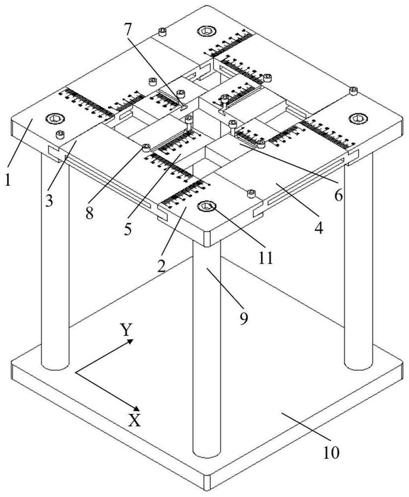
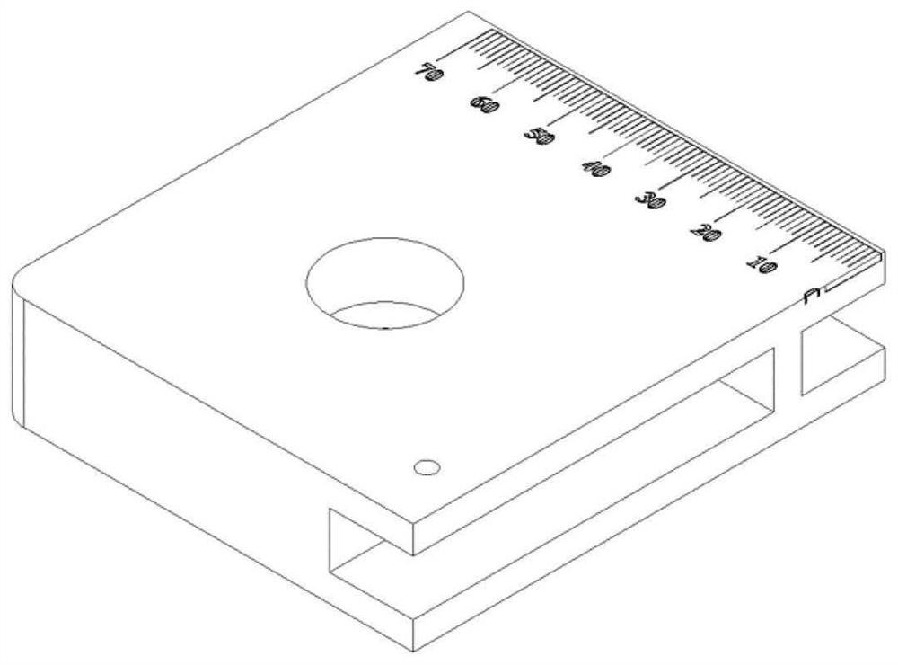
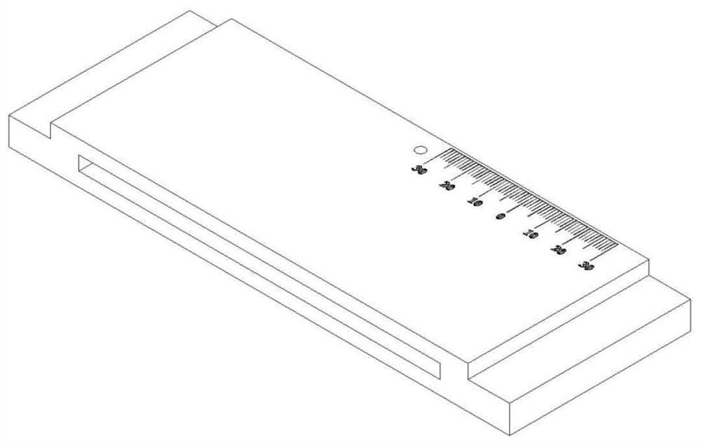
[0042] A drop hammer impact fixture with variable size, variable thickness, and variable impact point according to the present invention includes: the first upper base 1, on which there are 75mm×15mm×10mm guide rails, 65mm×15mm×10mm guide rails, 70mm scales, and M4 threaded holes and M10 threaded holes are used to provide support, guidance and positioning for the Y-direction position slider 3 and the X-direction position slider 4; the second upper seat 2 has a 75mm×15mm×10mm guide rail, a 65mm×15mm×10mm guide rail, 60mm scale, M4 threaded hole and M10 threaded hole, used to provide support, guidance and positioning for Y-direction position slider 3 and X-direction position slider 4; Y-direction position slider 3 has a 65mm×15mm×10mm slider Rail, 130mm×5mm×65mm guide rail, 30mm bidirectional scale and M4 threaded hole, used to cooperate with the first upper seat 1 and the second upper seat 2 to slide along the Y direction and provide support, guidance and positioning for the X-d...


PUM


Abstract

The invention discloses a drop hammer impact clamp with variable sample size, variable impact point and variable boundary conditions, and belongs to the field of impact test clamps. Comprising an upper base, a position sliding block, a boundary sliding block, a T-shaped sliding block, a supporting column and a base. The four upper seats are respectively fixed right above the base through the supporting columns and are positioned at four corners of the space rectangle; the base is used for being connected with a drop hammer impact testing machine; guide rails are arranged on two adjacent side surfaces of the inner side of the upper seat along the horizontal direction; the four position sliding blocks are respectively arranged on the guide rails of the four upper seats through the sliding rails to form edges of a space rectangle; the four boundary sliding blocks are installed on the guide rails of the four position sliding blocks through sliding rails correspondingly. The T-shaped sliding block is installed in the T-shaped guide rail of the boundary sliding block and can slide in the T-shaped guide rail, and a threaded hole is formed in the top of the T-shaped sliding block and matched with a bolt to press and position the edge of the sample. Impact of samples with the same size under the same position and different boundary conditions and impact of samples with different positions and different boundary conditions can be achieved.

Description

technical field [0001] The invention belongs to the field of impact test fixtures, in particular to a dropping weight impact fixture with variable sample size, variable impact point and variable boundary conditions. Background technique [0002] Composite materials have been widely used in the fields of aviation, spaceflight, ships and automobiles because of their excellent performance. In actual use, composite laminates and composite sandwich structures are easily damaged under low-velocity impact loads. In order to evaluate the impact resistance of composite laminates and composite sandwich structures, study the impact response of structures and materials under different low-speed impact loads and determine their damage tolerance, drop weight impact tests are usually required. [0003] The current impact test fixtures are usually designed according to the standard sample size (150mm×100mm) stipulated in ASTM D7136 and other standards. When the sample size changes, differe...

Claims


Application Information

Patent Timeline
Patent Type & Authority Applications(China)
IPC IPC(8): G01N3/30G01N3/04G01M7/08
CPCG01N3/30G01N3/04G01M7/08G01N2203/001Y02E30/30
Inventor 陈俊臻程龙蔡冠雄李玉军蒋建军
Owner NORTHWESTERN POLYTECHNICAL UNIV
Why Eureka
Try Eureka