Full-automatic crawler loader
A kind of slag removal machine, fully automatic technology, applied in mechanical cleaning, manufacturing tools, metal processing equipment, etc., can solve the problems of equipment displacement, inability to work, difficulty in adapting to design errors, etc., and achieve the effect of protecting safety and improving safety
- Summary
- Abstract
- Description
- Claims
- Application Information
AI Technical Summary
Problems solved by technology
Method used
Image
Examples
Embodiment 1
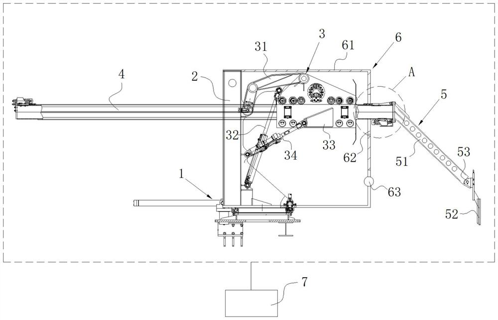
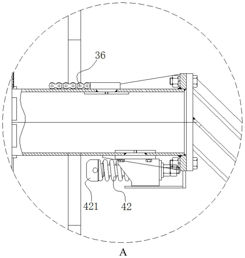
[0028] Embodiment 1: a kind of fully automatic slag removing machine, with reference to attached Figure 1~5 , including a rotary base 1, a bracket 2, a driving device 3, a telescopic arm 4 and a slag removal piece 5, the bracket 2 is fixed on the rotary base 1, the telescopic arm 4 is installed on the bracket 2 through the driving device 3, the The slag removal part 5 is installed at the end of the bracket 2; the driving device 3 includes a curved boom 31, a lifting telescopic rod 32, a sliding sleeve 33 and a swing telescopic rod 34, and the rear end of the boom 31 is hinged on the top of the bracket 2 , its front end is hinged on the top of the sliding sleeve 33, the bottom end of the lifting telescopic rod 32 is hinged on the bottom of the bracket 2, its top end is hinged on the front end of the boom 31, the rear end of the swinging telescopic rod 34 is hinged on the bracket 2, and its front end Hinged to the bottom of the sliding sleeve 33; the sliding sleeve 33 has a sli...
Embodiment 2
[0034] Embodiment 2: a kind of fully automatic slag removing machine, with reference to attached Figure 1~5 , including a rotary base 1, a bracket 2, a driving device 3, a telescopic arm 4 and a slag removal piece 5, the bracket 2 is fixed on the rotary base 1, the telescopic arm 4 is installed on the bracket 2 through the driving device 3, the The slag removal part 5 is installed at the end of the bracket 2; the driving device 3 includes a curved boom 31, a lifting telescopic rod 32, a sliding sleeve 33 and a swing telescopic rod 34, and the rear end of the boom 31 is hinged on the top of the bracket 2 , its front end is hinged on the top of the sliding sleeve 33, the number of the boom 31 is 2, and the two booms 31 are connected by a connecting rod 311, and the front ends of the two booms 31 are clamped on the top of the sliding sleeve 33 , here, the boom 31 is set to two and connected by connecting rod 311, which can strengthen the strength of the connection of the boom 31...
Embodiment 3
[0046] Embodiment 3: a kind of fully automatic slag removing machine, with reference to attached Figure 1~5 , including a rotary base 1, a bracket 2, a driving device 3, a telescopic arm 4 and a slag removal piece 5, the bracket 2 is fixed on the rotary base 1, the telescopic arm 4 is installed on the bracket 2 through the driving device 3, the The slag removal part 5 is installed at the end of the bracket 2; the driving device 3 includes a curved boom 31, a lifting telescopic rod 32, a sliding sleeve 33 and a swing telescopic rod 34, and the rear end of the boom 31 is hinged on the top of the bracket 2 , its front end is hinged on the top of the sliding sleeve 33, the number of the boom 31 is 2, and the two booms 31 are connected by a connecting rod 311, and the front ends of the two booms 31 are clamped on the top of the sliding sleeve 33 , here, the boom 31 is set to two and connected by connecting rod 311, which can strengthen the strength of the connection of the boom 31...
PUM
 Abstract
Description
Claims
Application Information
 - R&D
- Intellectual Property
- Life Sciences
- Materials
- Tech Scout
- Unparalleled Data Quality
- Higher Quality Content
- 60% Fewer Hallucinations
Browse by: Latest US Patents, China's latest patents, Technical Efficacy Thesaurus, Application Domain, Technology Topic, Popular Technical Reports.
© 2025 PatSnap. All rights reserved.Legal|Privacy policy|Modern Slavery Act Transparency Statement|Sitemap|About US| Contact US: help@patsnap.com


