Implant delivery device

A technology for delivery devices and implants, which is applied in the field of medicine and can solve problems such as inability to accurately determine the delivery position

Pending Publication Date: 2022-03-01
SHANGHAI MICROPORT CARDIOFLOW MEDTECH CO LTD
View PDF0 Cites 0 Cited by
  • Summary
  • Abstract
  • Description
  • Claims
  • Application Information

AI Technical Summary

Problems solved by technology

[0004] The purpose of the present invention is to solve the technical problem that the existing implant delivery device cannot accurately judge the delivery position when delivering the implant

Method used


Image

  • Implant delivery device
  • Implant delivery device
  • Implant delivery device

Examples


Embodiment Construction

[0050] An implant delivery device proposed by the present invention will be described in further detail below in conjunction with the accompanying drawings and specific embodiments. The advantages and features of the present invention will become clearer from the following description. It should be noted that all the drawings are in a very simplified form and use imprecise scales, and are only used to facilitate and clearly assist the purpose of illustrating the embodiments of the present invention. In addition, the structures shown in the drawings are often a part of the actual structures. In particular, each drawing needs to display different emphases, and sometimes uses different scales.

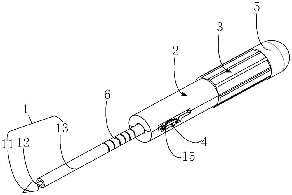
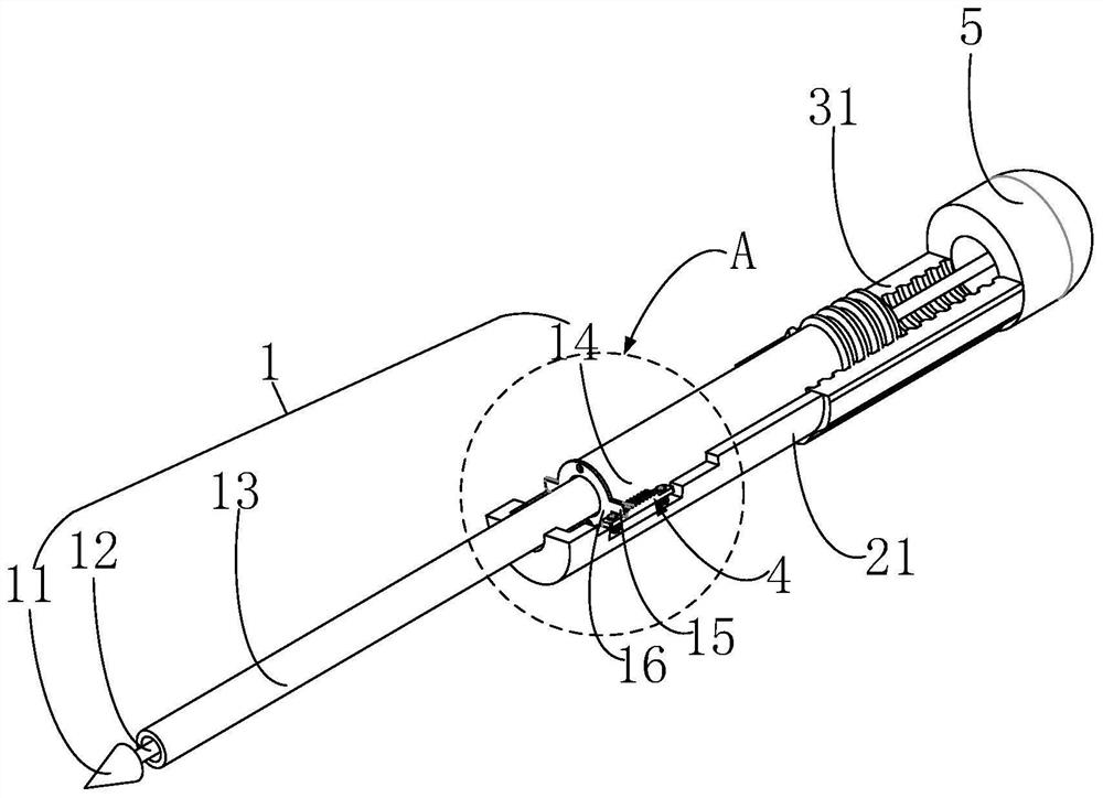
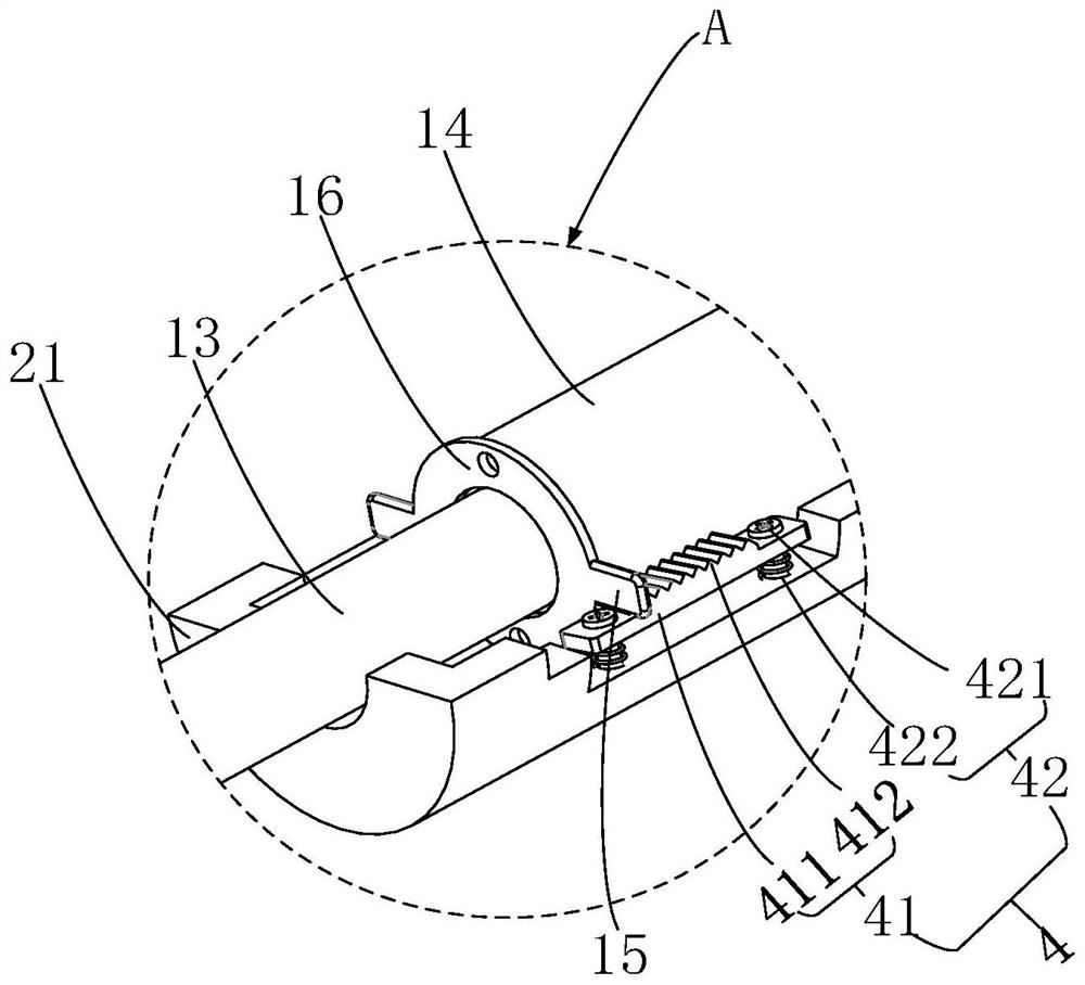
[0051] figure 1 It is a structural schematic diagram of an indicating scale provided on the outer tube of the implant delivery device in an embodiment of the present invention; figure 2 It is a partial structural diagram of the implant delivery device in an embodiment of the present i...


PUM


Abstract

According to the implant conveying device, the poking piece is arranged on the inner pipe or the outer pipe, the sound prompting assembly is arranged on the fixing structure, and therefore when the inner pipe or the outer pipe provided with the poking piece moves to drive the poking piece to move to the sound prompting assembly, the sound prompting assembly acts on the inner pipe or the outer pipe provided with the poking piece to make a sound. Therefore, when a doctor performs an implantation operation, the position of the inner tube or the outer tube after movement is determined according to the sound made by the sound prompt assembly.

Description

technical field [0001] The invention relates to the technical field of medicine, in particular to an implant delivery device. Background technique [0002] With the aging of my country's population, there are more and more elderly patients with valvular disease and patients with multiple risk factors such as hypertension, diabetes, and cerebrovascular disease. For the traditional surgical treatment of valvular disease, it is necessary to saw the sternum, establish extracorporeal circulation, and complete the valve replacement operation under cardiac arrest. However, the risk of surgical heart valve replacement under cardiopulmonary bypass is high for elderly patients with multiple risk factors. About 30% of patients give up surgery for valve replacement due to various reasons such as advanced age, poor left ventricular function, and serious complications. Therefore, for such patients, transcatheter valve replacement without thoracotomy, extracorporeal circulation, cardiac ...

Claims


Application Information

Patent Timeline
Patent Type & Authority Applications(China)
IPC IPC(8): A61F2/24
CPCA61F2/2466A61F2/24A61F2/95
Inventor 贾士奇梅杰林兴刘世红陈国明
Owner SHANGHAI MICROPORT CARDIOFLOW MEDTECH CO LTD
Why Eureka
Try Eureka