Guiding structure of minimally invasive surgery cutting anastomat

A guiding structure, minimally invasive surgery technology, applied in the field of medical devices, can solve the problems of high difficulty risk factor, complications, normal tissue accidental injury, etc., to reduce the risk of stenosis, improve the efficiency of suturing, and overcome the effects of time-consuming

Pending Publication Date: 2022-03-01
王冬
View PDF0 Cites 0 Cited by
  • Summary
  • Abstract
  • Description
  • Claims
  • Application Information

AI Technical Summary

Problems solved by technology

[0003] In the process of operating a laparoscopic cutting stapler, such as the operation of esophagojejunostomy, the current clinical practice is to place the staple cartridge splint below the tissue to be cut and extend into the jejunum, and the anvil above to extend into the esophagus. Cutting and anastomosis operation; however, due to the actual operating angle, the obstruction of other tissues in front of the cutting stapler, and the influence of the width and angle of the laparoscopic cutting stapler, it is often difficult to insert the front end of the cutting stapler into the esophagus, and the cutting stapler successfully entered It takes 5-30 minutes to reach the inside of the esophagus, and often requires very complicated and fine adjustments, which is prone to various side injuries and even serious postoperative complications
At present, the commonly used operation method is to use the front end of the cutting stapler to insert into the esophagus, as close as possible to the tube wall, but even so, it often enters the esophageal dissection by mistake, resulting in poor anastomosis and postoperative complications, and the result of anastomosis failure
The operation of the whole cutting and stapler is difficult, and the damage to the jejunum is relatively large, and it is easy to cause postoperative complications such as jejunal stenosis. damage
In the prior art, in the process of minimally invasive surgery, it usually takes a long time to confirm, the accuracy is not good, it is not conducive to the operation, the operation time is prolonged, the efficiency is reduced, the difficulty and risk factor are high, and there are medical risks

Method used


Image

  • Guiding structure of minimally invasive surgery cutting anastomat
  • Guiding structure of minimally invasive surgery cutting anastomat
  • Guiding structure of minimally invasive surgery cutting anastomat

Examples


Embodiment 1

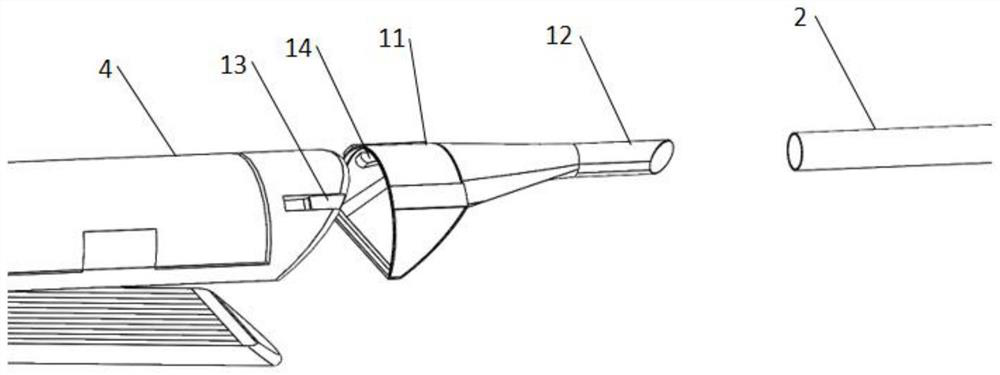
[0043] Please refer to Figure 1-Figure 3 , a guiding structure of a minimally invasive surgical cutting stapler in this embodiment, which includes a guiding assembly; the guiding assembly includes a guiding head 1 and a connecting head, and the guiding head 1 is arranged at the head end of the nail cartridge splint 4; The guide head 1 is correspondingly connected with the adapter head, and the adapter head protrudes from the inside of the esophagus; the guide head 1 and the staple cartridge splint 4 are flexibly connected through the first connecting piece; the guide head 1 is set to coincide with the head end of the staple cartridge splint 4 The first connecting pipe 11, the first end of the first connecting pipe 11 is connected to the head end of the staple cartridge splint 4, and the second end of the first connecting pipe 11 is connected to the adapter; in this way, the adapter is stretched out of the esophagus and reused The introducer 1 extends into the affected area an...

Embodiment 2

[0050] Please refer to Figure 4-Figure 7 , on the basis of Embodiment 1, this embodiment increases the following technical features: a second connector 16 is set at the second end of the first connector 12, and the second connector 16 is movably connected with the first connector 12; the second connection The second end of the head 16 is provided with an accommodating space for the first connecting head 12 to protrude into and be fixed; this kind of flexible connection can realize the replacement of the second connecting head 16 . The second connector 16 is plugged or threaded to the first connector 12 , the connection is set as a friction surface during the plug connection, and the connection is provided with a screw thread during the threaded connection, so as to avoid detachment during use.

[0051] The second connector 16 is elastically connected to the first connector 12; the second connector 16 and the first connector 12 are connected by a spring 161, one end of the spr...

Embodiment 3

[0054] Please refer to Figure 8-Figure 10 , on the basis of Embodiment 1, this embodiment adds the following technical features: a third connector 17 is set between the first connector 12 and the second connector 16, and the third connector 17 and the first connector 12 are movable connection, the third connecting head 17 is flexibly connected with the second connecting head 16; the setting of the third connecting head 17 increases the elasticity when the first connecting pipe 11 and the connecting head are connected, that is, when the guide head 1 and the connecting head are docked successfully and extend After entering the inside of the esophagus, a buffer space is provided for the position between the 4 head ends of the staple cartridge splint and the connecting head.

[0055] The third connection head 17 includes a connection section one 171 connecting the first connection head 12, and a connection section two 172 connecting the second connection head 16; the connection s...


PUM


Abstract

The invention relates to a guiding structure of a minimally invasive surgery cutting anastomat. The guiding structure comprises a guiding assembly. The guiding assembly comprises a guiding head and a receiving head, and the guiding head is arranged at the head end of the nail bin clamping plate; the guide head is correspondingly connected with the receiving head, and the receiving head extends out of the esophagus; the guide head and the nail bin clamping plate are movably connected through a first connecting piece. The guide head is a first connecting pipe matched with the head end of the nail bin clamping plate, the first end of the first connecting pipe is connected with the head end of the nail bin clamping plate, and the second end of the first connecting pipe is connected with the receiving head. The receiving head extends out of the esophagus, the guide head extends into the affected part and is correspondingly connected with the receiving head, so that the nail bin clamping plate and the guide head enter the esophagus along the receiving head, the problem that the front end of the anastomat enters the esophagus difficultly and time is consumed clinically is effectively solved, and the risk that the front end of the anastomat extends into the esophagus in a manner of being attached to the wall of a stomach tube to cause poor anastomosis or even failure is avoided; the method has the advantages of high accuracy, high docking speed and high success rate, and shows huge time advantage and brought follow-up safety advantage.

Description

technical field [0001] The invention belongs to the technical field of medical devices, and in particular relates to a guide structure for a minimally invasive surgery cutting stapler. Background technique [0002] Laparoscopic cutting and stapler is suitable for resection, transection and anastomosis of tissues in abdominal, gynecological, pediatric and thoracic surgery, and can also be used for resection and transection of liver parenchyma, liver blood vessels and gallbladder ducts. [0003] In the process of operating a laparoscopic cutting stapler, such as the operation of esophagojejunostomy, the current clinical practice is to place the staple cartridge splint below the tissue to be cut and extend into the jejunum, and the anvil above to extend into the esophagus. Cutting and anastomosis operation; however, due to the actual operating angle, the obstruction of other tissues in front of the cutting stapler, and the influence of the width and angle of the laparoscopic cu...

Claims


Application Information

Patent Timeline
Patent Type & Authority Applications(China)
IPC IPC(8): A61B17/11A61B17/00A61B90/11
CPCA61B17/1114A61B17/00234A61B90/11
Inventor 王冬
Owner 王冬
Why Eureka
Try Eureka