Pediatric tongue depressor
A tongue depressor and pediatric technology, applied in gymnastics equipment, muscle training equipment, body cavity massage equipment, etc., can solve the problems of single tongue coating force detection method, inconvenient detection for children, and inability to form data from the results
- Summary
- Abstract
- Description
- Claims
- Application Information
AI Technical Summary
Problems solved by technology
Method used
Image
Examples
Embodiment 1
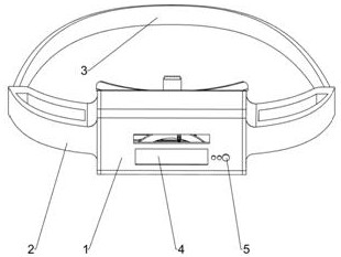
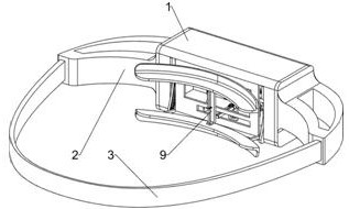
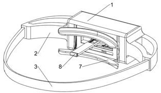
[0042] A pediatric tongue depressor, such as figure 1 , figure 2 , image 3 , Figure 4 and Figure 23 As shown, it includes an installation frame 1, a connecting frame 2, a fixing belt 3, a display screen 4, a control module 5, a stretching mechanism 7 and a tongue coating testing mechanism 8, and the left and right walls of the installation frame 1 are equipped with connecting frames 2. A fixed belt 3 is arranged between the rear walls of each connecting frame 2, and the fixed belt 3 is a detachable elastic belt. The lower part of the front wall of the installation frame 1 is embedded with a display screen 4, and the lower part of the front wall of the installation frame 1 is provided with a control module 5. , the control module 5 is located on the right side of the display screen 4, the control module 5 is connected to the remote control terminal through the Internet of Things communication network, the left and right parts of the rear wall of the installation frame 1 ...
Embodiment 2
[0045] On the basis of Example 1, such as Figure 5-Figure 15 As shown, the spreading mechanism 7 includes a first connecting plate 701, an upper tooth plate 702, an arc frame 703, an arc slide rail 705, a sliding block 706, a second connecting plate 707, a lower tooth plate 708, and a first spring 709 , the servo motor 710, the first gear 711 and the teeth 712, the left and right sides of the rear wall of the installation frame 1 are equipped with a first connecting plate 701, the first connecting plate 701 is located on the upper side of the second opening 61, two first The upper tooth plate 702 is arranged between the rear parts of the connecting plate 701, and the left and right parts of the inner bottom of the installation frame 1 are provided with arc-shaped frames 703, and the arc-shaped frames 703 on the left and right sides are respectively located in the first openings 6 on the left and right sides. Inside, the inner walls of the arc frame 703 on the left and right s...
Embodiment 3
[0060] On the basis of Example 2, such as Figure 16-22 As shown, the tongue tip test mechanism 9 is also included, and the tongue tip test mechanism 9 includes a support frame 901, a second electric push rod 902, an L-shaped plate 903, a moving block 904, a fixed block 905, a hollow tube 906, a rotating shaft 908, a pin Rod 909 and tip of tongue test parts, the bottom of the installation frame 1 is equipped with a support frame 901 at the front and rear. 902, the second electric push rod 902 is electrically connected with the control module 5, the telescopic end of the second electric push rod 902 is fixedly connected with an L-shaped plate 903, and the front part of the right wall of the L-shaped plate 903 is equipped with a moving block 904, and the moving block 904 There is a fixed block 905 on the right of the front and rear sides of the support frame 901, and a hollow tube 906 is arranged between the upper part of the support frame 901. The hollow tube 906 is located on ...
PUM
 Abstract
Description
Claims
Application Information
 - R&D Engineer
- R&D Manager
- IP Professional
- Industry Leading Data Capabilities
- Powerful AI technology
- Patent DNA Extraction
Browse by: Latest US Patents, China's latest patents, Technical Efficacy Thesaurus, Application Domain, Technology Topic, Popular Technical Reports.
© 2024 PatSnap. All rights reserved.Legal|Privacy policy|Modern Slavery Act Transparency Statement|Sitemap|About US| Contact US: help@patsnap.com


