
Interlocking device of high-voltage switchgear mechanism

A high-voltage switch and interlock device technology, which is applied in high-voltage/high-current switches, electric switches, high-voltage air circuit breakers, etc., can solve the problems of opening, misoperation and closing of the transmission end of the switch, and achieve the goal of improving operational safety Effect

Pending Publication Date: 2022-02-25
JIANGSU DAYBRIGHT INTELLIGENT ELECTRIC CO LTD
View PDF1 Cites 0 Cited by
  • Summary
  • Abstract
  • Description
  • Claims
  • Application Information

AI Technical Summary

Problems solved by technology

[0004] The purpose of the present invention is to provide a high-voltage switchgear mechanism interlocking device to solve the existing high-voltage switchgear mechanism interlocking device proposed in the above-mentioned background technology, because the switch drive end may be closed or opened by mistake due to misoperation dangerous question

Method used


Image

  • Interlocking device of high-voltage switchgear mechanism
  • Interlocking device of high-voltage switchgear mechanism
  • Interlocking device of high-voltage switchgear mechanism

Examples


Embodiment Construction

[0023] The following will clearly and completely describe the technical solutions in the embodiments of the present invention with reference to the accompanying drawings in the embodiments of the present invention. Obviously, the described embodiments are only some, not all, embodiments of the present invention.

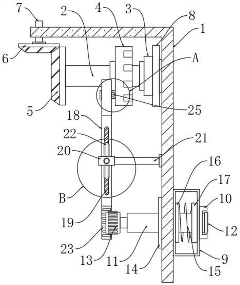
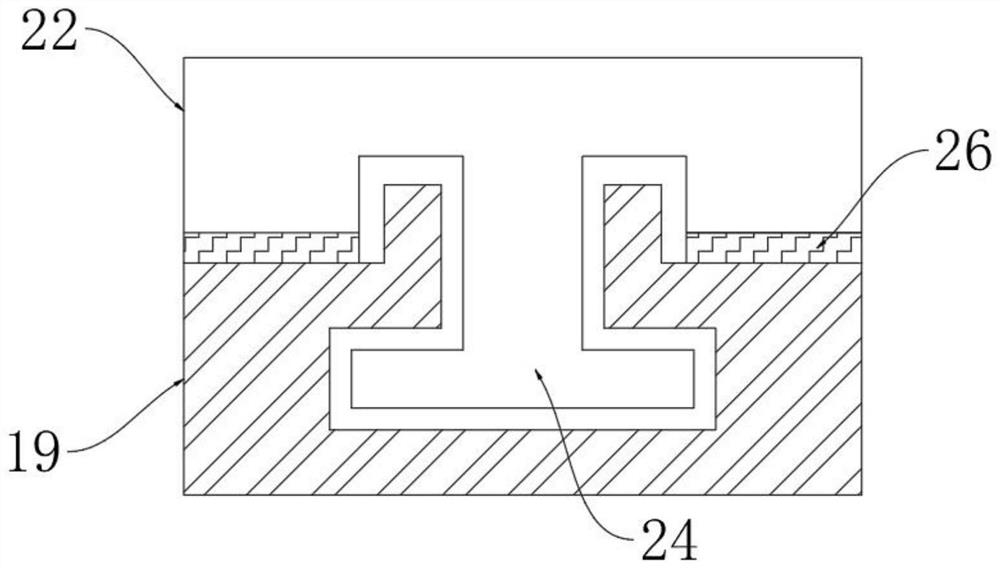
[0024] see Figure 1-6 , an embodiment provided by the present invention: a high-voltage switchgear mechanism interlocking device, including a chassis cabinet 1, a countershaft 2 is arranged inside the chassis cabinet 1, a bearing 3 is arranged at one end of the countershaft 2, and the countershaft 2 The transmission wheel 4 is arranged on the outside, and the transmission wheel 4 and the auxiliary shaft 2 are integrally formed. One side of the bearing 3 is provided with a cabinet coupling plate 8, and the cabinet coupling plate 8 is connected to the chassis cabinet 1 by a screw, and the bearing 3 is connected to the cabinet. Cabinet connecting shaft plate 8 shaft co...


PUM


Abstract

The invention discloses an interlocking device of a high-voltage switch equipment mechanism, relates to the technical field of electrical equipment, and aims to solve the problem that a switch transmission end of an existing interlocking device of the high-voltage switch equipment mechanism may be mistakenly closed or opened due to misoperation. An auxiliary shaft is arranged on the inner side of the case cabinet, a bearing is arranged at one end of the auxiliary shaft, a transmission wheel is arranged on the outer side of the auxiliary shaft, a cabinet body connecting shaft plate is arranged on one side of the bearing, a first bevel gear is arranged at the other end of the auxiliary shaft, and a second bevel gear is arranged at the upper end of the first bevel gear. An interlocking transmission shaft is arranged at the upper end of the second bevel gear, a deflection transmission shaft is arranged on one side of a transmission wheel, a transmission rod is arranged on the outer side of one end of the deflection transmission shaft, a switch bin is arranged on the outer side of the case cabinet, a rotary knob shell is arranged on one side of the switch bin, and a main shaft is arranged in the switch bin; and a knob is arranged at one end of the main shaft.

Description

technical field [0001] The invention relates to the technical field of electrical equipment, in particular to a high-voltage switchgear mechanism interlocking device. Background technique [0002] In traditional devices, such as application number: 201811543783.2; named: a high-voltage switchgear mechanism interlocking device. The device includes: a travel switch, an interlocking fixed plate, a guide fixed plate, a guide plate, an aluminum alloy square rod, a grounding baffle, a limit expansion pin, and an interlocking rod. The interlocked fixed plate is fixedly connected to the guide fixed plate, The travel switch is fixedly installed on the interlocking fixed plate. The guide fixed plate is provided with an aluminum alloy square rod in the longitudinal direction and a guide plate in the horizontal direction. A first interlock spring is set between the grounding baffle and the limit expansion pin, the bottom end is provided with an interlock lever, and the guide plate is p...

Claims


Application Information

Patent Timeline
Patent Type & Authority Applications(China)
IPC IPC(8): H01H33/48H01H33/02
CPCH01H33/02H01H33/48
Inventor 陶广耀陶文庸张国徽张双雄王志马开春单俊方兴未牛晓冬赵飞王亚奇陈欢张磊
Owner JIANGSU DAYBRIGHT INTELLIGENT ELECTRIC CO LTD
Learn More