
Aviation container applied to aviation loading

A container and aviation technology, applied in the field of aviation containers, can solve the problems of inability to disassemble the box body, high transportation cost, occupying a large space, etc., and achieve the effect of convenient stacking transportation, reducing transportation cost and saving space.

Active Publication Date: 2022-02-25
春秋航空技术发展江苏有限公司
View PDF13 Cites 0 Cited by
  • Summary
  • Abstract
  • Description
  • Claims
  • Application Information

AI Technical Summary

Problems solved by technology

[0003] This kind of container is a fixed box after production. This kind of box cannot be disassembled. It needs to take up a lot of space during transportation, which is not convenient enough and the transportation cost is high. Most of the existing boxes are fixed space. structure, and cannot be expanded, therefore, the present invention proposes an air container applied to air loading to solve the problems existing in the prior art

Method used


Image

  • Aviation container applied to aviation loading
  • Aviation container applied to aviation loading
  • Aviation container applied to aviation loading

Examples


Embodiment 1

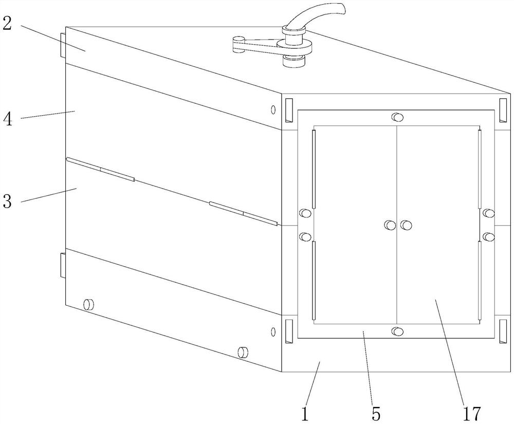
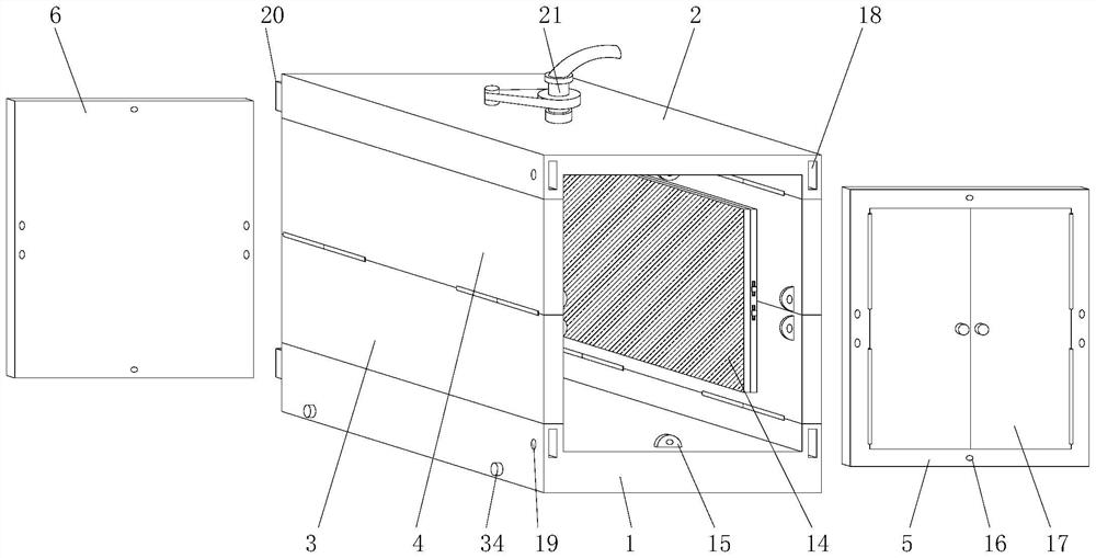
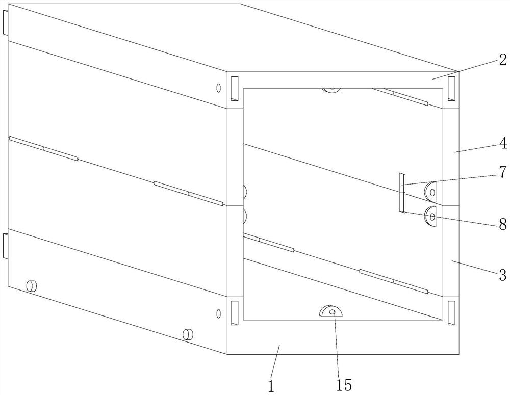
[0029] according to figure 1 , 2 , 3, 4, and 5, this embodiment proposes an air container for airborne loading, including a first U-shaped plate 1 and a second U-shaped plate 2, and the two above the first U-shaped plate 1 The first baffle 3 is hinged inside the sides, and the second baffle 4 is hinged on both sides of the bottom of the second U-shaped plate 2. The first baffles 3 of the two groups are respectively connected with the second baffles of the two groups. The baffle plate 4 is externally hinged, and the first U-shaped plate 1, the second U-shaped plate 2, the first baffle plate 3 and the second baffle plate 4 form a box body, and the front and rear ends of the box body are respectively equipped with door panels 5 and The fixed plate 6, the seams at both ends of the first baffle plate 3 and the second baffle plate 4 are provided with a card slot 7, and a fixed slot 8 is provided in the card slot 7;

[0030] Both sides of the inside of the box are provided with sup...

Embodiment 2

[0036] according to figure 1 , 2, 3, 4, and 6, this embodiment proposes an air container for airborne loading, including a first U-shaped plate 1 and a second U-shaped plate 2, and the two above the first U-shaped plate 1 The first baffle 3 is hinged inside the sides, and the second baffle 4 is hinged on both sides of the bottom of the second U-shaped plate 2. The first baffles 3 of the two groups are respectively connected with the second baffles of the two groups. The baffle plate 4 is externally hinged, and the first U-shaped plate 1, the second U-shaped plate 2, the first baffle plate 3 and the second baffle plate 4 form a box body, and the front and rear ends of the box body are respectively equipped with door panels 5 and The fixed plate 6, the seams at both ends of the first baffle plate 3 and the second baffle plate 4 are provided with a card slot 7, and a fixed slot 8 is provided in the card slot 7;

[0037] Both sides of the inside of the box are provided with supp...


PUM


Abstract

The invention provides an aviation container applied to aviation loading, and relates to the technical field of containers. The aviation container comprises a first U-shaped plate and a second U-shaped plate, first baffles are hinged to the two sides of the upper portion of the first U-shaped plate, second baffles are hinged to the two sides of the bottom of the second U-shaped plate, the two sets of first baffles are externally hinged to the two sets of second baffles correspondingly, and the first U-shaped plate, the second U-shaped plate, the first baffles and the second baffles form a box body. A splicing folding type installation mode is adopted, during transportation, a fixing plate and a door plate can be taken down, and the first baffles and the second baffles are folded inwards, so that the box body is folded, space is saved, and transportation cost is reduced. When installation is needed, only the first baffles and the second baffles need to be folded outwards to form the box body, a supporting block is clamped into a clamping groove, a sliding block is pushed, a clamping rod is inserted into a fixing groove, a supporting plate supports the box body, the door plate and the fixing plate are matched for fixing, and stability is guaranteed.

Description

technical field [0001] The invention relates to the technical field of containers, in particular to an air container applied to air loading. Background technique [0002] At present, due to the advantages of fast, convenient and high safety, air transportation is more and more widely used in logistics transportation. In order to facilitate transportation management, the goods to be transported can be packed into air containers. The existing air containers are usually aluminum The container is made of aluminum alloy profiles through welding to form a container frame, and then the aluminum alloy skin is fixed and covered outside the container frame by welding to form an air container; [0003] This kind of container is a fixed box body after production. This kind of box body cannot be disassembled. It needs to occupy a lot of space during transportation, which is not convenient enough, and the transportation cost is high. Most of the existing boxes are fixed space type. The s...

Claims


Application Information

Patent Timeline
Patent Type & Authority Applications(China)
IPC IPC(8): B65D88/52B65D90/02B65D90/22B65D90/18
CPCB65D88/528B65D90/02B65D90/22B65D90/18
Inventor 张恺金钰蒋京涛
Owner 春秋航空技术发展江苏有限公司
Learn More