Mold, molding system, and mold manufacturing method

A technology for molds and molded products, used in manufacturing tools, casting molding equipment, cores, etc., can solve the problems of oil-based mold release agent viscosity change, thin layer thickness, unbalanced heating state of mold release agent, etc., to achieve inflow resistance. Small size, high manufacturing efficiency, smooth flow effect

Active Publication Date: 2022-02-18
SHIPPO KANAGATA INDS +2
View PDF8 Cites 0 Cited by
  • Summary
  • Abstract
  • Description
  • Claims
  • Application Information

AI Technical Summary

Problems solved by technology

However, if an oil-based release agent is poured into a hollow tube in a high-temperature state, a new problem arises: the release agent that comes into contact with the surface of the hollow tube is released earlier than the release agent that flows in the center of the tube. When heated, the heating state of the release agent tends to become unbalanced, and the properties such as the viscosity of the oil-based release agent tend to change
[0006] If the metal powder layer is irradiated with a laser beam at an equal scanning interval and the scanning speed is adjusted and melted and solidified to form a low-density region composed of continuous fine pores, there will be a continuity of pores in places where the layer thickness is thicker. Sex prone to uneven tendencies
Therefore, if the layer thickness of the low-density region is increased, it will be difficult to control the inflow rate of the release agent, and unevenness will be observed in the seepage of the release agent.
In addition, in order to improve the manufacturing efficiency of the mold itself, there is a problem that the layer thickness of the molten and solidified mold part needs to be reduced.

Method used


Image

  • Mold, molding system, and mold manufacturing method
  • Mold, molding system, and mold manufacturing method
  • Mold, molding system, and mold manufacturing method

Examples


Embodiment 1

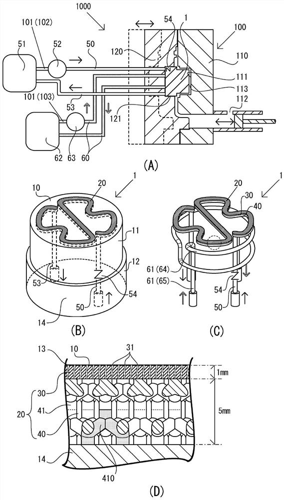
[0056] In Example 1, refer to Figure 1 to Figure 4 as well as Figure 9 , a mold having a liquid infiltration unit and a molding system including the mold are described. figure 1 An explanatory diagram illustrating the structure of the mold is shown. figure 1 (A) in (A) is an explanatory diagram showing the overall structure of a molding system including a mold. figure 1 (B) is a perspective view showing the right surface of the nested mold 1 having the liquid infiltration unit as the upper side, figure 1 (C) in (C) is a perspective view which only shows the internal structure of this nest mold. figure 1 (D) in shows figure 1 Partial enlarged cross-sectional view of the part of the dotted circle in (C). In the following examples, the cross-sectional view of the mold and the perspective view of the liquid path portion constituting the liquid wetting unit are shown with the molding surface side up in the figure.

[0057] Figure 9 (A) in (A) shows a cross-sectional photo...

Embodiment 2

[0091] In Example 2, refer to Figure 5 A second example of a three-dimensional mesh structure will be described. Figure 5 (A) in (A) shows a perspective view of the second unit structure. Figure 5 (B) in shows the Figure 5 A perspective view of a state in which the second unit structures shown in (A) are arranged side by side in the horizontal direction. exist Figure 5 In , for easy understanding, the cell structures arranged in the rear row are colored and shown.

[0092] The second unit structure 70 constituting the three-dimensional network structure is composed only of thin shafts 71 inclined obliquely. Specifically, eight thin shafts 71, 71... extend obliquely from the center of gravity of the cube 72 inscribed with the second unit structure toward each apex of the cube 72 (refer to Figure 5 in (A)). An example is shown in which the length of one side of the cube 72 is about 1.8 mm, and the length of one side of the cross section of the thin shaft 72 is about ...

Embodiment 3

[0095] In Example 3, refer to Image 6 A third example of a three-dimensional mesh structure will be described. Image 6 (A) in (A) is a perspective view showing the third unit structure 80 . Image 6 (B) in the Image 6 A perspective view of a state in which the unit structures shown in (A) are arranged side by side in the horizontal direction. exist Image 6 In , a part of the third unit structure is shown in color.

[0096] Like the second unit structure, the third unit structure 80 constituting the three-dimensional mesh structure is composed only of obliquely inclined thin shafts 81 . Specifically, the third unit structure 80 is formed by combining the intersecting ring structure 82 and the second unit structure 70 of Embodiment 2 (refer to Figure 5 in (A)). In the intersecting ring structure 82, the two rings 85 formed by the thin shaft 81 are perpendicular to each other, and the respective overlapped parts 86 form a whole. The thin shaft 81 passes through the cub...


PUM

PropertyMeasurementUnit
thicknessaaaaaaaaaa
thicknessaaaaaaaaaa
distanceaaaaaaaaaa

Abstract

[Problem] To provide a mold, a molding system, and a mold manufacturing method which make it possible to easily and effectively spread mold release components of a mold release agent onto an inner surface of a mold without degrading the mold release agent, even with oil-based mold release agents, and which can achieve high manufacturing efficiency. [Solution] A pair of molds for molding a molded product in a gap therebetween is caused to be provided with a liquid path portion and a liquid infiltration layer configured by melting and solidifying metal powders, and a mold release agent is caused to be infiltrated into the gap. Specifically, the liquid infiltration layer is caused to be a thin layer having, at a high density, a liquid infiltration tube which is communicated with the molded surface and has a minute diameter. The liquid path portion is caused to have a 3D mesh structure having a meshed thin shaft, and is arranged along the liquid infiltration layer. The mold release agent is distributed while being in contact with the 3D mesh structure, thereby exerting such an advantageous effect that the mold release agent is not heated unevenly, and deterioration thereof is suppressed. When a form is adopted in which melting and solidifying are not performed with an axial direction of the thin shaft horizontal, this is preferable because easy melting and solidifying are achieved without breaking the thin shaft.

Description

technical field [0001] The present invention relates to a mold capable of suppressing the amount of the mold release agent used even if it is an oil-based mold release agent, and wherein the mold release component of the mold release agent is easily and effectively spread on the inner surface of the mold. Moreover, it relates to the molding system which can suppress the usage-amount of a release agent and shorten molding work by having the said mold. Moreover, it also relates to the mold manufacturing method which can manufacture the mold which can make the surface of a mold easy to infiltrate a mold release agent with high manufacturing efficiency. Background technique [0002] The mold is used as a frame for forming a resin molded product or a metal molded product. Conventionally, in order to allow the molded product to be released from the mold smoothly, a mold release agent was sprayed on the inner surface of the mold every time the molded product was cast, and the mold...

Claims


Application Information

Patent Timeline
Patent Type & Authority Applications(China)
IPC IPC(8): B22D17/20B22D17/22B22F3/105B22F3/16B33Y10/00B29C33/58
CPCB22C9/06B22D17/22B22F3/105B22F3/16B29C33/38B29C33/58B33Y10/00B33Y80/00B22D17/20
Inventor 松冈宽高古本达明新川真人
Owner SHIPPO KANAGATA INDS
Why Eureka
Try Eureka