
Charger with heat dissipation mechanism

A heat dissipation mechanism and charger technology, which is applied in the direction of current collectors, electric vehicles, electrical components, etc., can solve the problem of low heat dissipation efficiency of chargers, achieve the effect of improving heat dissipation effect, improving heat dissipation efficiency, and prolonging service life

Pending Publication Date: 2022-02-18
天长市天越电子有限公司
View PDF0 Cites 0 Cited by
  • Summary
  • Abstract
  • Description
  • Claims
  • Application Information

AI Technical Summary

Problems solved by technology

[0003] This application provides a charger with a heat dissipation mechanism, which is used to solve the problem of low heat dissipation efficiency of chargers in the prior art

Method used


Image

  • Charger with heat dissipation mechanism
  • Charger with heat dissipation mechanism
  • Charger with heat dissipation mechanism

Examples


Embodiment Construction

[0030] The implementation manner of the present application will be further described in detail below with reference to the drawings and embodiments. The following examples are used to illustrate the present application, but cannot be used to limit the scope of the present application.

[0031] In the description of the embodiments of the present application, it should be noted that the terms "center", "vertical", "transverse", "upper", "lower", "front", "rear", "left", "right" , "vertical", "horizontal", "top", "bottom", "inner", "outer" and other indicated orientations or positional relationships are based on the orientations or positional relationships shown in the drawings, and are only for the convenience of describing this The application embodiments and simplified descriptions do not indicate or imply that the devices or elements referred to must have a specific orientation, be constructed and operated in a specific orientation, and therefore should not be construed as ...


PUM


Abstract

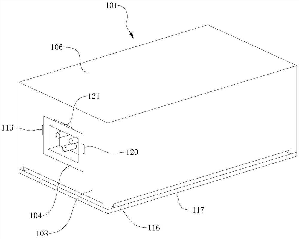
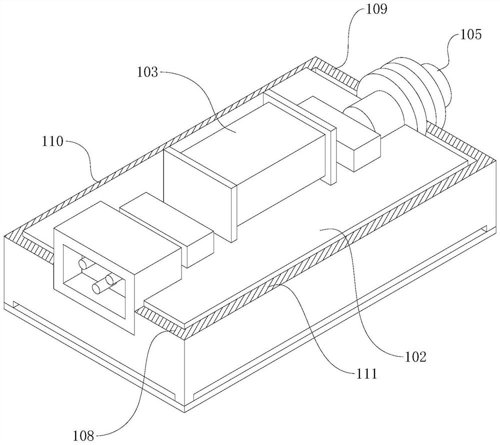
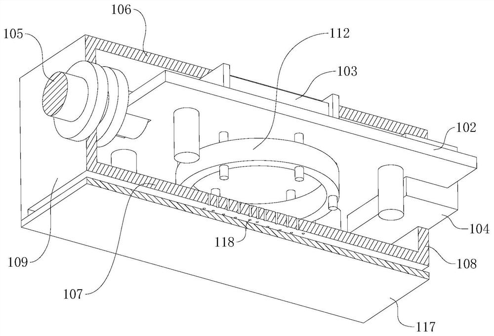
The invention provides a charger with a heat dissipation mechanism. The charger comprises a shell, a PCB, an electronic component, a charging interface and a power line. The charger with the heat dissipation mechanism further comprises the heat dissipation mechanism, the heat dissipation mechanism comprises an electric fan, an air inlet and an air outlet, the electric fan is located in the shell and electrically connected with a circuit on the PCB, the PCB is horizontally arranged, the electric fan is located between the PCB and the bottom plate, and a shell of the electric fan is fixedly connected with the upper surface of the bottom plate. The air inlet is formed in the front end plate, penetrates through the front end plate and is located between the PCB and the top plate; the exhaust port is formed in the bottom plate and penetrates through the bottom plate, an air outlet of the electric fan faces the exhaust port, and an air inlet of the electric fan is communicated with the space between the PCB and the bottom plate; and a gap is formed between the edge of the PCB and the inner wall of the shell. Compared with a charger in the prior art, the charger with the heat dissipation mechanism is higher in heat dissipation efficiency.

Description

technical field [0001] The present application relates to the technical field of chargers, in particular to a charger with a heat dissipation mechanism. Background technique [0002] Electric bicycle chargers in the prior art usually include a housing, a PCB board, a plug and a charging interface. The PCB board is fixed inside the housing. both ends of the body. During the charging process, plug the plug into the socket, connect one end of the charging cable to the charging interface, and connect the other end of the charging cable to the charging interface of the electric bicycle to realize charging the electric bicycle. However, during the charging process, the electronic components integrated on the PCB will generate heat, and the heat is blocked inside the shell, and the heat dissipation performance is poor, and it is difficult to dissipate to the outside air, resulting in a high temperature of the charger and reducing the work of the charger. efficiency and shorten th...

Claims


Application Information

Patent Timeline
Patent Type & Authority Applications(China)
IPC IPC(8): H02J7/00H05K7/20
CPCH02J7/0042H05K7/20909Y02T10/70Y02T10/7072
Inventor 张春红
Owner 天长市天越电子有限公司
Learn More