Eureka AIR delivers breakthrough ideas for toughest innovation challenges, trusted by R&D personnel around the world.

Mobile charging device for wireless cold compress instrument

A technology of mobile charging and cold compress, which is applied to circuit devices, battery circuit devices, current collectors, etc., can solve the problems of inability to use the cold compress at any time, and the cold compress can not be used, and achieve the effect of preventing damage and being unable to use.

Pending Publication Date: 2022-02-18
ZUODIAN IND (HUBEI) CO LTD
View PDF0 Cites 0 Cited by
  • Summary
  • Abstract
  • Description
  • Claims
  • Application Information

AI Technical Summary

Problems solved by technology

[0004] For the cold compress device in the prior art, the internal refrigeration element is used to produce cold air without preparing towels and ice packs, which can effectively avoid water stains during the cold compress and cause inconvenience to the user, but because the cold compress device needs to be plugged into the power socket when in use Only by supplying power to the cold compress sheet can the cold air be released. When the user carries the cold compress device to an environment where there is no power supply socket for power supply, the cold compress device cannot be used, and the user cannot use the cold compress device at any time. The present invention Provides a mobile charging device for a wireless cooling device

Method used


Image

  • Mobile charging device for wireless cold compress instrument
  • Mobile charging device for wireless cold compress instrument
  • Mobile charging device for wireless cold compress instrument

Examples


Embodiment Construction

[0026] In order to make the technical means, creative features, goals and effects achieved by the present invention easy to understand, the present invention will be further described below in conjunction with specific embodiments.

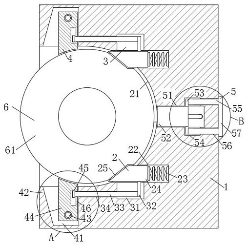
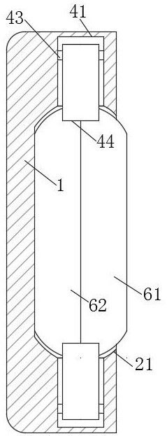
[0027] Such as Figure 1-Figure 7 As shown, a mobile charging device for a wireless cold compress device according to the present invention includes a charging stand 1, a snap-in mechanism 2 is provided on the surface of the charging stand 1, and a linkage mechanism 3 is arranged inside the snap-in mechanism 2, A clamping mechanism 4 is provided inside the clamping mechanism 2 , a charging mechanism 5 is provided on the surface of the charging base 1 , and a cold compress device 6 is clamped inside the clamping mechanism 2 .

[0028] Specifically, the snap-in mechanism 2 includes a snap-in groove 21, two positioning slots 22 are symmetrically opened on the inner wall of the snap-in slot 21, and springs 23 are fixedly connected to the inside of the...


PUM


Abstract

The invention relates to the technical field of cold compress instruments, in particular to a mobile charging device for a wireless cold compress instrument, which comprises a charging seat, a clamping mechanism is arranged on the surface of the charging seat, a linkage mechanism is arranged in the clamping mechanism, a clamping mechanism is arranged in the clamping mechanism, and a charging mechanism is arranged on the surface of the charging seat. The cold compress instrument is clamped in the clamping mechanism, the cold compress instrument is clamped through the formed clamping groove, then the cold compress instrument is rotated to enable the positioning insertion block to correspond to the fixed clamping groove, then the positioning insertion block is pushed through the spring to enable the positioning insertion block to be inserted into the clamping groove, then the cold compress instrument is fixed, and meanwhile the charging interface corresponds to the charging connector. And then the charging interface is connected with the charging connector to supply power to the cold compress instrument, so that the cold compress instrument can be charged through the charging seat at any time under the environment that the electric quantity of a battery in the cold compress instrument is used up and no power supply socket is used for supplying power, and the cold compress instrument is prevented from being unable to use.

Description

technical field [0001] The invention relates to the technical field of cold compresses, in particular to a mobile charging device for wireless cold compresses. Background technique [0002] Cold compress is one of the treatment methods, that is, apply ice packs or cold wet towels on the forehead, the back of the neck or the skin of the lesion, and apply it to the lesion. The main purpose is to promote local vasoconstriction, control the bleeding of small blood vessels and reduce the tension. The pain of the lump can achieve the effect of reducing swelling and relieving pain. For patients with high fever, applying it on the forehead and back of the neck can reduce body temperature and improve discomfort. It is more convenient to use. [0003] Existing cold compress devices produce cold air through the internal refrigeration elements without preparing towels and ice packs, effectively avoiding water stains during cold compresses and causing inconvenience to users. When the u...

Claims


Application Information

Patent Timeline
IPC IPC(8): H02J7/00H05K7/20
CPCH02J7/0044H05K7/20909
Inventor 朱江涛向文林邹加兵刘继辉汤颖颖许立黄子亮陈可夫张琦向文明郑国庆
Owner ZUODIAN IND (HUBEI) CO LTD
Why Eureka
Eureka Blog
Learn More