
Static detection device and method of phased array radar system

A phased array radar and static detection technology, which is applied in the field of radio frequency radar, can solve the problems of prolonging the phased array radar development cycle, high processing difficulty, and reducing test efficiency, so as to shorten the test time, save labor costs, and avoid labor costs. The effect of the test

Pending Publication Date: 2022-02-18
ZHEJIANG UNIV
View PDF0 Cites 0 Cited by
  • Summary
  • Abstract
  • Description
  • Claims
  • Application Information

AI Technical Summary

Problems solved by technology

Among them, the number of antenna units and channels of phased array radar ranges from hundreds to thousands or even tens of thousands. If it is processed into an integrated array, there will be problems such as high processing difficulty, poor maintainability, and low electromagnetic compatibility. Therefore, the traditional large-scale active phased array is composed of several sub-arrays
The traditional wave control system can realize the calculation and distribution of wave control codes. However, before the phased array radar starts to work, it is necessary to test all the channels individually to determine whether the channel of the TR component corresponding to each channel is working normally. It takes a lot of time to switch channels and make judgments, prolonging the development cycle of phased array radar
And for each TR component, the existing technology can only test the performance of the component on the fixture, when the component is welded to the antenna board, the performance cannot be directly tested
In addition, the entire radar system contains a large number of mounted TR components. The existing technology can only use a microwave anechoic chamber to test the entire system. Due to the lack of performance caused by welding problems, the test time will be further increased and the test efficiency will be reduced.

Method used


Image

  • Static detection device and method of phased array radar system
  • Static detection device and method of phased array radar system
  • Static detection device and method of phased array radar system

Examples


Embodiment 1

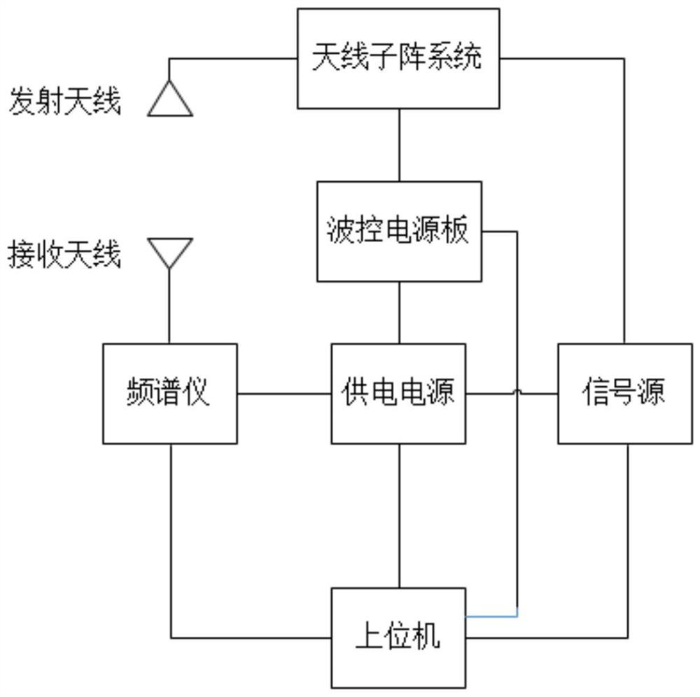
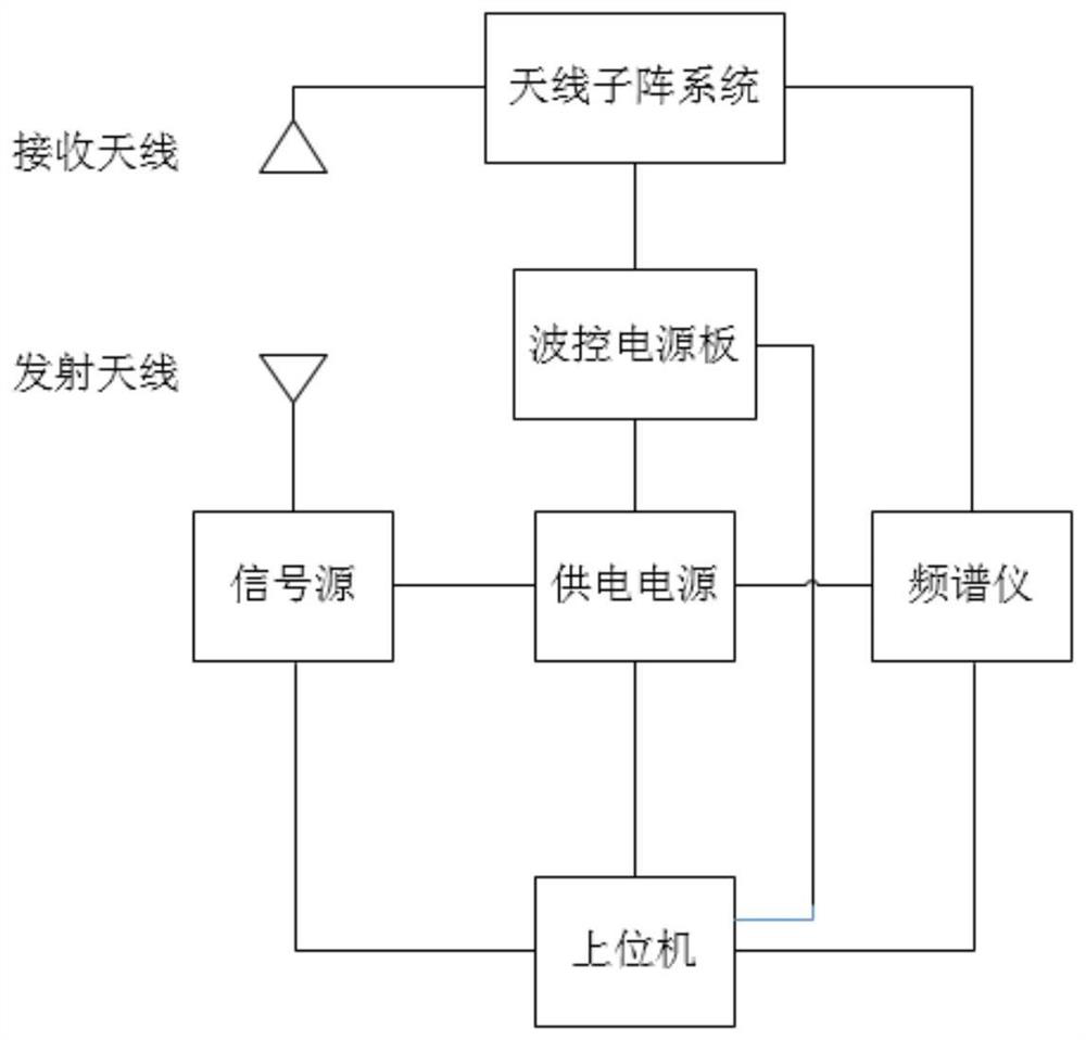
[0050] Such as figure 1 , 2 As shown, a static detection device for a phased array radar system includes a host computer, a power supply, a signal source, a spectrum analyzer, a wave control power supply board, an antenna sub-array system, a transmitting antenna, and a receiving antenna; wherein the host computer is connected to the power supply, The spectrum analyzer and the signal source are connected, and the host computer is also connected to the wave control power board through a low-voltage differential signal; the power supply is also connected to the spectrum analyzer, signal source, and wave control power board; the antenna sub-array system is connected to the wave control power board. It should be noted that the antenna sub-array system is also connected to the transmitting antenna and the signal source, and the corresponding spectrum analyzer is also connected to the receiving antenna to test the transmission performance of the antenna sub-array system; or the anten...


PUM


Abstract

The invention relates to static detection device and method for a phased array radar system. The device comprises an upper computer, a power supply, a signal source, a frequency spectrograph, a wave control power panel, an antenna sub-array system, a transmitting antenna and a receiving antenna; wherein the upper computer is respectively connected with the power supply, the frequency spectrograph and the signal source, and the upper computer is also connected with the wave control power panel through a low-voltage differential signal; the power supply is also respectively connected with the frequency spectrograph, the signal source and the wave control power supply board; the antenna sub-array system is connected with the transmitting antenna wave control power panel and the signal source respectively; and the frequency spectrograph is also connected with the receiving antenna. By arranging the wave control power supply board, the power supply and the upper computer, automatic detection of the antenna sub-array system is realized, manual testing is avoided, the labor cost is saved, the testing precision is improved, and the testing accuracy is ensured.

Description

technical field [0001] The invention relates to the field of radio frequency radar, in particular to a static detection device and method for a phased array radar system. Background technique [0002] As a new type of radar, active phased array radar has the characteristics of high pointing accuracy, strong anti-interference ability and high reliability. Compared with traditional mechanical scanning radar, it also has the advantages of no servo turntable, fast scanning speed and simultaneous Advantages such as multi-target detection. The active phased array radar antenna front is generally composed of multiple antenna units arranged according to certain rules, and each antenna unit is provided with a corresponding phase shifter and attenuator control. When working, it is necessary to control the phase and amplitude values ​​of all phase shifters and attenuators according to the beam pointing. Therefore, a beam control system is required to calculate and control the phase sh...

Claims


Application Information

Patent Timeline
IPC IPC(8): G01S7/40
CPCG01S7/40G01S7/4004
Inventor 曹赞扬宣银良王志宇
Owner ZHEJIANG UNIV
Learn More