
Direct-current volt-ammeter calibration device and calibration method

A technology of DC voltage and calibration device, applied in measuring devices, measuring electrical variables, instruments, etc., can solve the problem of unable to drive the pointer ammeter, etc., and achieve the effect of light weight, small size and strong driving ability

Pending Publication Date: 2022-02-18
苏州捷准计量技术有限公司
View PDF0 Cites 0 Cited by
  • Summary
  • Abstract
  • Description
  • Claims
  • Application Information

AI Technical Summary

Problems solved by technology

[0007] 3. At present, some pointer ammeters cannot be driven when using multi-function

Method used


Image

  • Direct-current volt-ammeter calibration device and calibration method
  • Direct-current volt-ammeter calibration device and calibration method
  • Direct-current volt-ammeter calibration device and calibration method

Examples


Embodiment 1

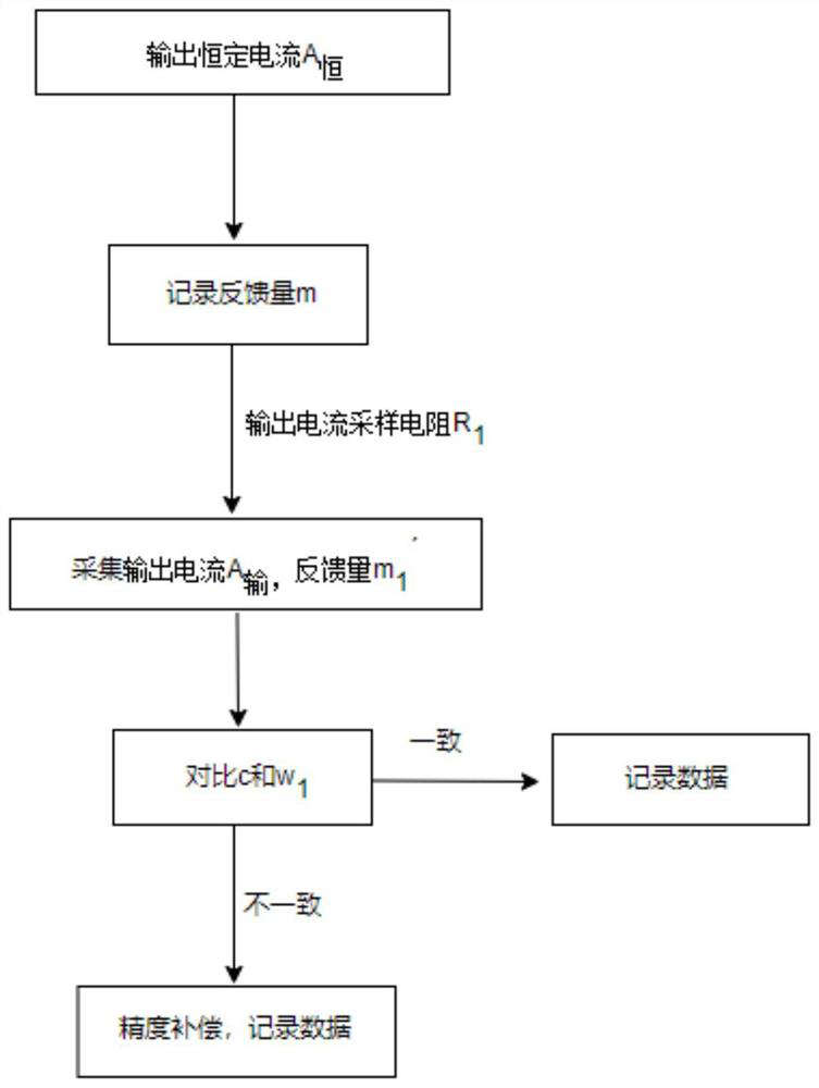
[0034] Such as figure 2 Shown, a DC ammeter calibration method, including the following steps:

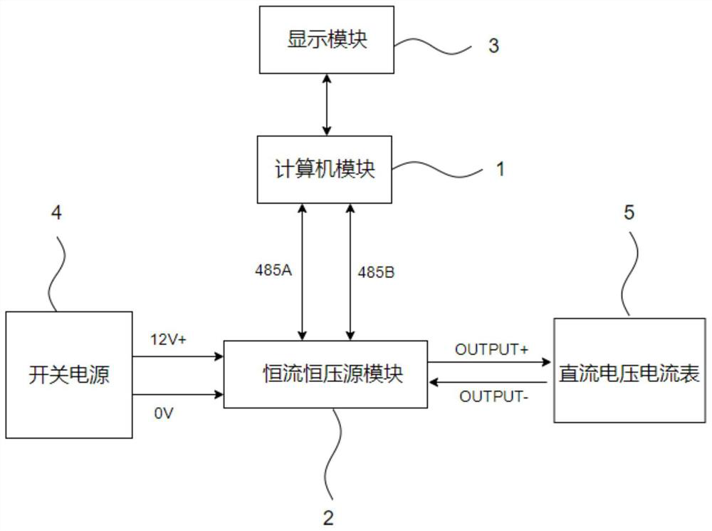
[0035] S 1 : Turn on the switching power supply to provide a current and voltage source for the constant current and constant voltage source module, and then the computer module sends an instruction to the constant voltage and constant current source module through the 485 protocol to output a constant current A 恒 ;

[0036] S 2 : Set the ideal calibration coefficient c=1, record the feedback m of the ammeter to the display module at this time, and then output a current sampling resistor R 1 , put the output current A 输 Sampling back, record the feedback m of the ammeter to the display module at this time 1 ′, forming negative feedback, the formula of the computer module is as follows:

[0037] where R is (R 1 , R 2 , R 3 ...), m 1 ', A 输 , Change with the change of R.

[0038] S 3 : match c with w 1 For comparison, the computer module finally sends data through th...

Embodiment 2

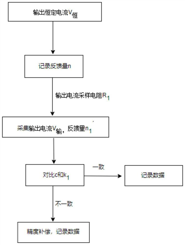
[0040] Such as image 3 As shown, a DC voltmeter calibration method includes the following steps:

[0041] S 1 : Turn on the switching power supply to provide a current and voltage source for the constant current and constant voltage source module, and then the computer module sends an instruction to the constant voltage and constant current source module through the 485 protocol to output a constant voltage V 恒 ;

[0042] S 2 : Set the ideal calibration coefficient c=1, record the feedback amount n that the voltmeter feeds back to the display module at this time, and then output a current sampling resistor R 1 , put the output voltage V 输 Sampling back, record the feedback amount n of the voltmeter to the display module at this time 1 ′, forming negative feedback, the formula of the computer module is as follows:

[0043] where R is (R 1 , R 2 , R 3 ...), n ′ and V 输 Varies with R.

[0044] S 3 : combine c with k 1 For comparison, the computer module finally sen...


PUM


Abstract

The invention discloses a direct-current volt-ammeter calibration device and a calibration method. The device comprises a computer module connected with a display module, and also comprises a constant-current and constant-voltage source module which is connected with a direct-current volt-ammeter and receives an instruction sent by the computer module, a switching power supply which is connected with the constant-current and constant-voltage source module and provides a current and voltage source for the constant-current and constant-voltage source module, and a display module which is connected with the computer module and displays the operation process and result of the computer module. The device is high in output constant voltage or constant current precision, small in size, light in weight and highly integrated. A plurality of required calibration points can be set for automatic output, and the magnitude of the required voltage or current can be manually and arbitrarily set and output to automatically adjust the corresponding output voltage. A set value is read back through communication, and a production report is collected and automatically recorded, so that the calibration efficiency is greatly improved, and paperless operation is realized. The coverage range is wide, and the driving capability is strong.

Description

technical field [0001] The invention relates to the field of electronic instrument measurement, in particular to a DC voltmeter calibration device and a calibration method thereof. Background technique [0002] The voltmeter is an instrument for measuring voltage. Its application fields include engineering measurement, conversion of large-scale integrated circuits, large-scale digital measurement, application of integrated circuits and other circuit applications. DC ammeter is an instrument used to measure the current intensity in DC circuit. Its application fields include solar photovoltaic power generation system, performance test of power distribution wire and cable factory in communication room, industrial DC control system, metallurgical industry, electroplating industry and electrolysis industry, wind power generation system And DC excitation system, etc. [0003] Digital display current and voltmeter is a current and voltage testing instrument with digital display fu...

Claims


Application Information

Patent Timeline
IPC IPC(8): G01R35/04
CPCG01R35/04
Inventor 陈启兵
Owner 苏州捷准计量技术有限公司
Learn More